Closed loop type wind power generation system

A wind power generation system and wind turbine technology, applied in wind power generation, wind turbines, wind turbine combinations, etc., can solve the problems of petrochemical energy shortage environment, pollution of alternative energy and other problems, achieve small wind energy loss, stable wind speed and wind pressure, improve The effect of efficiency

Inactive Publication Date: 2015-01-21
JIANGSU HONGXIN REVOLVING COMPENSATOR TECH
View PDF0 Cites 4 Cited by
  • Summary
  • Abstract
  • Description
  • Claims
  • Application Information

AI Technical Summary

Problems solved by technology

[0003] The purpose of the present invention is to invent a closed-loop wind power generation system for the current shortage of petrochemical energy, environmental pollution and the problems of alternative energy.

Method used


Image

  • Closed loop type wind power generation system
  • Closed loop type wind power generation system
  • Closed loop type wind power generation system

Examples


Embodiment 1

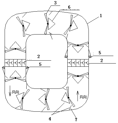
[0031] like figure 1 , 2 shown.

[0032] A closed-loop wind power generation system, which includes a circular or polygonal annular air duct 1, a blower array 2, and a wind generator 3. The annular air duct 1 can generate a wind tunnel effect, and is the place where the horizontal blade generator is installed , the height (diameter) of the barrel depends on the radius of the generator blades; the center surrounded by the annular air duct 1 can be installed with power transformation and transmission devices or greened. At least one blower array 2 is installed in the annular air duct 1, figure 1 Two blower arrays 2 are installed in it, and the blower arrays 2 are installed in the annular air duct to realize the unidirectional circulation of the air in the annular air duct, and form a wind generator blade in the annular air duct to generate The rotating wind force, the wind pressure and wind speed of the wind force are maintained within the set ratio range under the action of ...

Embodiment 2

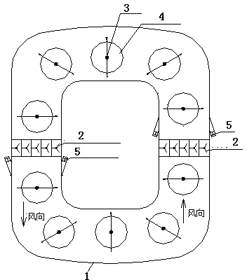
[0034] like image 3 , 4 shown.

[0035] A closed-loop wind power generation system, which includes a circular or polygonal annular air duct 1, a blower array 2 and a wind generator 3, the annular air duct 1 can produce a wind tunnel effect, and is the place where the vertical blade generator is installed , the cross-section of cylinder is the best with rectangle, and its height depends on the height of generator blade; The center surrounded by annular air duct 1 can install power transformation and transmission device or carry out greening. At least one blower array 2 is installed in the annular air duct 1, image 3 There are two blower arrays 2 installed in it, and the blower arrays 2 are installed in the said annular air duct 1, and are used to realize the one-way circulating flow of the air in the annular air duct, and form a driving wind power generation in the annular air duct. The wind force that the machine blade rotates, the wind pressure and wind speed of the wind...

Embodiment 3

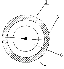
[0037] like Figure 5 , 6 shown.

[0038]The difference between this embodiment and Embodiments 1 and 2 is that in addition to the steel structure and plastic structure, the annular air duct 1 also adopts a pure concrete structure or a brick-concrete structure and is arranged in a multi-layer manner. In 1, every floor can be installed with a phased array blower and wind generator, such as Figure 5 As shown, each layer works independently of each other, and each layer of annular air duct 1 can also be connected into a spiral air duct through a spiral structure, such as Image 6 As shown, the annular air duct at the bottom is provided with an air inlet, while the annular air duct at the highest level is provided with an air outlet. The spiral structure arrangement can use the effect of the updraft to reduce the power of the blower, save current, and also occupy an area. The advantages of small space, low construction cost, and no impact on the beautiful environment can be re...


PUM


Abstract

A closed loop type wind power generation system is characterized by comprising an annular air barrel (1), at least one air blower array (2) and a plurality of wind driven generators (3). The air blower arrays (2) are arranged in the annular air barrel and are used for enabling air in the annular air barrel to achieve single-direction circulating flow and generate wind in the annular air cylinder; wherein the wind can drive blades of the wind driven generators to rotate. The pressure and speed of the wind are maintained to be within the set proportionality range under the action of the air blower arrays so as to ensure the power generation efficiency and stability of the wind driven generators (3). The wind driven generators (3) are arranged in the annular air barrel (1) and are driven by the blades to rotate to generate power. The closed loop type wind power generation system has the advantages of being capable of continuously generating power, and being clean and environmentally-friendly.

Description

technical field [0001] The invention relates to a power generation technology, in particular to a wind power generation technology, in particular to a closed-loop wind power generation system. Background technique [0002] At present, with the increasing shortage of fossil energy in the world and the need for environmental protection, there is an urgent need for alternative cleansing. The existing natural wind power, photovoltaic, nuclear energy and hydropower generation cannot be vigorously developed due to certain limitations. Among them, wind power generation is one of the ideal clean energy sources at present, but it is greatly affected by environmental factors. It must have an open site and sufficient stable wind power. If the wind power is unstable, it will cause a greater impact on the power grid. Therefore, , it can only be used as a supplement to petrochemical power and cannot work stably for a long time. Therefore, finding a new wind power generation method and...

Claims


Application Information

Patent Timeline
Patent Type & Authority Applications(China)
IPC IPC(8): F03D9/00
CPCF03D1/02F03D1/04F03D9/25Y02E10/72
Inventor 宋章根
Owner JIANGSU HONGXIN REVOLVING COMPENSATOR TECH
Why Eureka
Try Eureka