A method for improving the utilization efficiency of cooling capacity during liquefied natural gas gasification

A technology of liquefied natural gas and liquefied natural gas, which is applied in applications, heating methods, household appliances, etc., can solve the problems of long cold water transportation distance, low cooling conversion efficiency, and many heat exchange processes, so as to reduce the use of pipelines and pumps, High utilization efficiency of cooling capacity and the effect of reducing manufacturing cost

Active Publication Date: 2017-08-22
谢红飞
View PDF8 Cites 0 Cited by
  • Summary
  • Abstract
  • Description
  • Claims
  • Application Information

AI Technical Summary

Problems solved by technology

However, this method has the following problems: 1. LNG must be heated before it can be gasified, and external energy is used; although cold water is used as the cooling medium, the transportation distance of cold water in the pipeline is too long, and the loss of cooling capacity is large, and then enters the indoor air conditioner The heat exchange with the air in the system further loses the cooling capacity. The heat exchange process and the cooling loss are large, resulting in a low conversion efficiency of the cooling capacity released when the liquefied natural gas is converted into a gaseous state, only about 40%.
2. Due to the large water consumption, the water needs to be pumped into the air-conditioning system on each floor, the structure is complex and the engineering volume is large, and the loss of cooling capacity during the transportation process is also large

Method used


Image

  • A method for improving the utilization efficiency of cooling capacity during liquefied natural gas gasification

Examples


Embodiment Construction

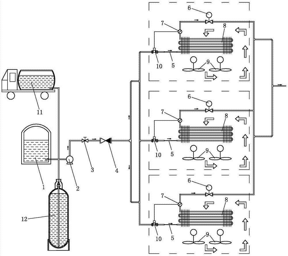
[0017] like figure 1 Shown is the process flow diagram of the utilization method of the cooling capacity when the liquefied natural gas is gasified in the present invention, the cooling capacity utilization method of the present invention is as follows: the liquefied natural gas at -160 ° C is transferred from the low-temperature liquid storage tank 1 or the tank car 11 of the liquefied natural gas station or The liquefied natural gas cylinder 12 is pressurized by the pump 2 (pressurized to 0.5-0.8 MPa), passes through the stop valve 3 and the check valve 4, and then is transported to the capillary 5 through the pipeline. Pipe 8, the liquefied natural gas can be turned into gaseous natural gas without any external energy in the coil 8, the natural gas absorbs heat in the process of changing from liquid to gas, so that the temperature of the coil 8 decreases, and the temperature of the air around the outer wall of the coil 8 decreases, The fan 9 located directly below the coil ...


PUM


Abstract

Provided is a liquefied natural gas gasification cooling capacity utilizing method. Liquefied natural gas is delivered to a capillary tube from a low temperature liquid storage tank, a tank car or a liquefied natural gas steel bottle after being subjected to pump pressurization, flows out from the capillary tube and enters a coil pipe arranged at the indoor top. The liquefied natural gas can be converted into gas state natural gas without any additional energy in the coil pipe. The natural gas absorbs heat in the process from the liquid state to the gas state to enable the temperature of the coil pipe to be reduced, the temperature of the air surrounding the outer wall of the coil pipe is reduced, cold air surrounding the outer wall of a fan suction coil pipe arranged below the coil pipe and air circulating to the place above the coil pipe are blown indoors, and the gas state natural gas leaves the coil pipe and is delivered into natural gas users' houses through pipelines. Due to the fact that the liquefied natural gas enters the coil pipe through the capillary tube, the effect that the natural gas can meet the cold capacity required by an indoor cooler in the delivery process is achieved without any additional energy, a large amount of energy is saved, and the method is simple in structure and low in manufacture and use cost.

Description

technical field [0001] The invention relates to a method for improving the utilization efficiency of cooling capacity during gasification of liquefied natural gas. Background technique [0002] Patent No. 00128935.7 discloses a method for utilizing the cooling capacity of liquefied natural gas during gasification. This method uses normal temperature water to gasify liquefied natural gas, making it into gaseous natural gas, which is transported to users through pipelines; normal temperature water makes liquefied natural gas gas At the same time, the temperature is reduced to low-temperature cold water and introduced into the indoor air-conditioning system as a cold source, avoiding the use and energy consumption of traditional Freon. However, this method has the following problems: 1. LNG must be heated before it can be gasified, and external energy is used; although cold water is used as the cooling medium, the transportation distance of cold water in the pipeline is too lon...

Claims


Application Information

Patent Timeline
Patent Type & Authority Patents(China)
IPC IPC(8): F24F5/00F25D3/10
CPCF24F5/0035F24F2005/0039
Inventor 谢红飞
Owner 谢红飞
Why Eureka
Try Eureka