a wide angle lens

A wide-angle lens and lens technology, which is applied in the field of wide-angle lenses, can solve the problems of restricting product versatility and wide application, the cost of thermally offset glass lenses, and the lens cannot work normally, and achieve the effect of light weight, low cost and good tolerance

Active Publication Date: 2017-04-26
GOERTEK OPTICAL TECH CO LTD
View PDF8 Cites 0 Cited by
  • Summary
  • Abstract
  • Description
  • Claims
  • Application Information

AI Technical Summary

Problems solved by technology

[0002] With the advancement of technology, consumer electronics products have higher and higher requirements for the application of wide-angle lenses, especially in various environments: such as snowy mountains, high temperature and other harsh environments, the expectations for lens performance are higher. It will cause a large back focus shift to the lens of general plastic structure, which will affect the quality of imaging, and seriously cause blurred imaging, unstable system parameters, and failure modes such as the lens not working properly.
[0003] The main method commonly used at present to eliminate thermal offset is to use a large number of glass materials. Since the refractive index of glass materials changes little with temperature, it can well eliminate the influence of temperature on the focal length of the system. However, the use of glass materials in mass production First, the cost of wide-angle lens is relatively high, and second, it is difficult to correct the distortion to the ideal range. If glass aspheric surface is used, the cost and production capacity will greatly restrict the versatility and wide-range application of the product.
[0004] How to avoid the thermal offset caused by the use of plastic lenses and the high cost and difficult to correct distortion caused by the use of glass lenses has become a difficult problem to be overcome

Method used


Image

  • a wide angle lens
  • a wide angle lens
  • a wide angle lens

Examples


Embodiment 1

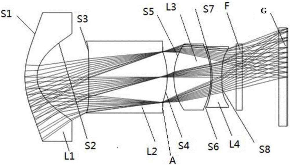
[0049] Please refer to figure 1The schematic diagram of the structure of the wide-angle lens according to Embodiment 1 of the present invention includes: a front group and a rear group in sequence along the light incident direction, the front group includes a first negative lens L1 and a second positive lens L2, and the rear group includes a similar cemented Lens group: the third positive lens L3 and the fourth negative lens L4, specifically: the first negative lens L1 has a first surface S1 convex to the object side and a second surface S2 concave to the image side, and is located at the beginning of the lens;

[0050] The second positive lens L2 has a third surface S3 concave toward the object side and a fourth surface S4 convex toward the image side;

[0051] The third positive lens L3 has a fifth surface S5 convex to the object side and a sixth surface S6 convex to the image side;

[0052] The fourth negative lens L4 has a seventh surface S7 concave toward the object side...


PUM

PropertyMeasurementUnit
refractive indexaaaaaaaaaa

Abstract

The invention provides a wide-angle lens. The wide-angle lens comprises a front set and a rear set in sequence in the light incidence direction. The front set comprises a first negative lens and a second positive lens. The rear set comprises a similar bonding lens set including a third positive lens and a fourth negative lens. Specifically, the first negative lens is provided with a first surface protruding towards an object space and a second surface concaved towards an image space and is located at the starting end of the lens. The second positive lens is provided with a third surface concaved towards the object space and a fourth surface protruding towards the image space. The third positive lens is provided with a fifth surface protruding towards the object space and a sixth surface protruding towards the image space. The fourth negative lens is provided with a seventh surface concaved towards the object space and an eighth surface concaved towards the image space. According to reasonable arrangement of all the elements, the thicknesses of the lenses are equal to the air interval thickness, the lenses are easy to process and form in shape, the requirement for eliminating distortion at a large field angle is met, and meanwhile the quality of high-temperature and low-temperature imaging is optimized and corrected; besides, the cost is low, the structure is simple and miniaturization is achieved.

Description

technical field [0001] The invention relates to the technical field of optical lens design, in particular to a wide-angle lens. Background technique [0002] With the advancement of technology, consumer electronics products have higher and higher requirements for the application of wide-angle lenses, especially in various environments: such as snowy mountains, high temperature and other harsh environments, the expectations for lens performance are higher. It will cause a large back focus shift to the general plastic lens, which will affect the quality of the imaging, serious imaging blur, unstable system parameters, resulting in failure modes such as the lens not working properly. [0003] The main method commonly used at present to eliminate thermal offset is to use a large number of glass materials. Since the refractive index of glass materials changes little with temperature, it can well eliminate the influence of temperature on the focal length of the system. However, th...

Claims


Application Information

Patent Timeline
Patent Type & Authority Patents(China)
IPC IPC(8): G02B13/18G02B13/06G02B13/00G02B1/04
CPCG02B1/00G02B1/041G02B13/004G02B13/006G02B13/06G02B13/18
Inventor 杨春
Owner GOERTEK OPTICAL TECH CO LTD
Why Eureka
Try Eureka