Display and electronic device

A display and edge area technology, applied in the electronic field, can solve the problem of poor display effect of borderless display, achieve the effect of improving display effect, complete picture, and avoiding blurred pixels

Inactive Publication Date: 2015-01-21
TIANJIN SAMSUNG ELECTRONICS CO LTD +1
View PDF6 Cites 6 Cited by
  • Summary
  • Abstract
  • Description
  • Claims
  • Application Information

AI Technical Summary

Problems solved by technology

[0005] The embodiment of the present invention solves the problem of poor display effect of the borderless display in the prior art by providing a display and an electronic device

Method used


Image

  • Display and electronic device
  • Display and electronic device
  • Display and electronic device

Examples


Embodiment Construction

[0027] In order to solve the technical problem of poor display effect of the borderless display in the prior art, an embodiment of the present invention provides a display and electronic equipment, the general idea is as follows:

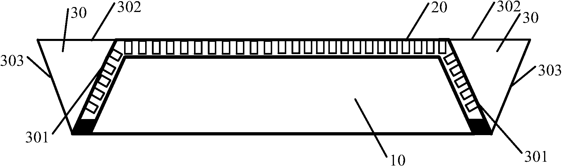
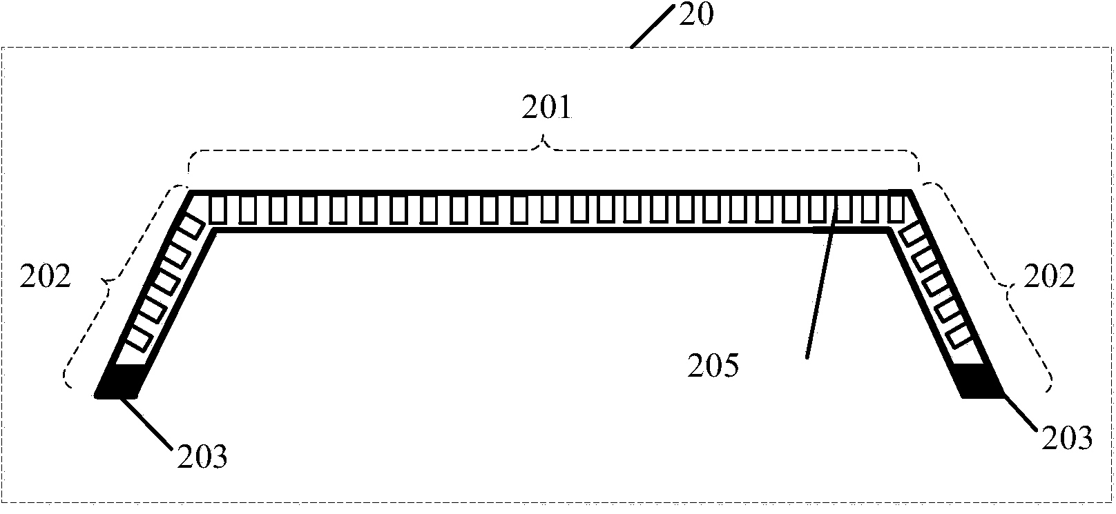
[0028] The liquid crystal panel is formed by bending the edge area of ​​the liquid crystal panel inward at an acute angle, and a prism refractor is added above the edge area to refract the display screen in the edge area through the refraction of light. The blurring of pixels in the edge area and the proportional distortion of the entire display screen in the prior art are avoided, and a borderless display with better display effect is formed.

[0029] In order to better understand the above-mentioned technical solution, the above-mentioned technical solution will be described in detail below in conjunction with the accompanying drawings and specific implementation methods.

[0030] refer to figure 1 as shown, figure 1 It is a cross-sectional view...


PUM

PropertyMeasurementUnit
angleaaaaaaaaaa

Abstract

The invention discloses a display and an electronic device and solves the technical problem of poor display effects of a rimless display in the prior art. According to the technical scheme, the display comprises a backlight layer providing a display backlight source, a liquid crystal panel comprising a first region and an edge region arranged on at least one side of the first region, and a prism refracting body formed above the edge region, wherein the liquid crystal panel covers the upper surface of the backlight layer, the included angle between the extended line of the first region and the edge region is an acute angle, the edge region is covered by the bent portion of the upper surface, and one side surface of the prism refracting body is arranged in the same plane with the first region. The light of the edge region is emitted in the direction perpendicular to the plane of the first region after being refracted by the prism refracting body.

Description

technical field [0001] The invention relates to the field of electronic technology, in particular to a display and electronic equipment. Background technique [0002] With the requirements of the occasions where the display is to be used, it is hoped that the display can get rid of the constraints of the frame and be able to display without a frame to meet more display requirements of the display. [0003] At present, a borderless display includes a display screen and an optical member covering the display screen. The optical member includes an optical flat panel and a light guide assembly arranged around the optical flat panel. The light guide assembly includes several light guide sheets stacked together. The sheets are arranged from the side of the optical flat plate to the direction away from the optical flat plate. The light guide sheets are stacked in an expanded shape. There is an air gap between the light guide sheets. The light guide sheet of the component is guided...

Claims


Application Information

Patent Timeline
Patent Type & Authority Applications(China)
IPC IPC(8): G02F1/1335G02F1/13357
CPCG02F1/133606G02F1/133607
Inventor 冯雷
Owner TIANJIN SAMSUNG ELECTRONICS CO LTD
Why Eureka
Try Eureka