Transparent projection screen

A projection screen and transparent technology, applied in optics, instruments, projection devices, etc., can solve problems such as complex manufacturing process, high cost of liquid crystal materials, and restriction of display brightness diffraction efficiency, and achieve cost reduction, easy batch production, and increase light energy The effect of utilization

Active Publication Date: 2015-01-21
SUZHOU UNIV
View PDF14 Cites 71 Cited by
  • Summary
  • Abstract
  • Description
  • Claims
  • Application Information

AI Technical Summary

Problems solved by technology

This type of projection screen has a certain degree of transparency, but its display brightness is severely restricted by the diffraction efficiency, and the utilization rate of light energy is low.
Chinese

Method used


Image

  • Transparent projection screen
  • Transparent projection screen
  • Transparent projection screen

Examples


Embodiment 1

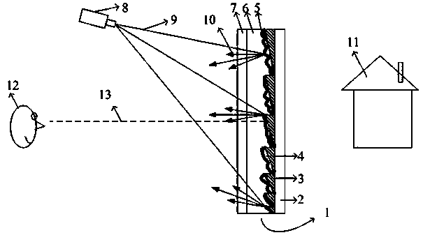
[0022] See attached figure 1 , which is a schematic diagram of a random diffusion transparent projection screen and its projection display structure in this embodiment.

[0023] The transparent projection screen 1 is composed of a first base material layer 2 , a focusing structure 3 , a diffusion structure 4 , a partially reflective film structure 5 , a refractive index matching layer 6 and a second base material layer 7 . The focusing structure 3 is a prism structure located on the lower surface of the first substrate layer 2, the diffusion structure 4 is a random phase structure located on the surface of the focusing structure 3, the partially reflective film structure 5 is a dielectric film structure coated on the surface of the random phase structure 4, and the refractive index matching layer 6 is filled between the second substrate layer 7 and the partially reflective film structure 5, and the refractive index of the material is consistent with that of the materials of t...

Embodiment 2

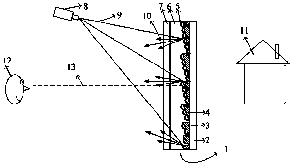
[0030] See attached image 3 , is a schematic diagram of a microlens diffusion transparent projection screen and its projection display structure in this embodiment.

[0031] The transparent projection screen 1 is composed of a first base material layer 2 , a focusing structure 3 , a diffusion structure 4 , a partially reflective film structure 5 , a refractive index matching layer 6 and a second base material layer 7 . The focusing structure 3 is a V-groove structure located on the lower surface of the first substrate layer 2, the diffusion structure 4 is a microlens array structure located on the surface of the focusing structure 3, and the partially reflective film structure 5 is a metal film coated on the surface of the microlens structure 4. The matching layer 6 is filled between the second substrate layer 7 and the partially reflective film structure 5 , and the refractive index of its material is consistent with that of the materials of the focusing structure and the di...

Embodiment 3

[0038] See attached Figure 4 , is a schematic diagram of an anti-reflection random diffusion transparent projection screen and its projection display structure in this embodiment.

[0039] The transparent projection screen 1 is composed of a first substrate layer 2 , a focusing structure 3 , a diffusion structure 4 , a partially reflective film structure 5 , a refractive index matching layer 6 , a second substrate layer 7 , and an antireflection structure 14 . The focusing structure 3 is a prism structure located on the lower surface of the first substrate layer 2, the diffusion structure 4 is a random phase structure located on the surface of the focusing structure 3, and the partially reflective film structure 5 is a dielectric film structure coated on the random phase On the surface of the structure 4, the refractive index matching layer 6 is filled between the second substrate layer 7 and the partially reflective film structure 5, and the refractive index of its material ...


PUM


Abstract

The invention discloses a transparent projection screen. The transparent projection screen comprises base material layers, wherein focusing structures and diffusing structures are distributed on the lower surface of the first base material layer and combined with the first base material layer, light rays from a projection system are focused on the position where an observer is located through the focusing structures and are diffused into an observation area on the position where the observer is located by the diffusing structures, the focusing structures and the diffusing structures are plated with a partial reflection film structure, a reflective index matching layer is combined with the surface of the partial reflection film structure and covers the surface of the partial reflection film structure, the reflective index of the reflective index matching layer is identical with the reflective index of materials of the focusing structures and the diffusing structures, and the second base material layer is combined with the surface of the reflective index matching layer and covers the surface of the reflective index matching layer. By the adoption of the projection screen, the observer can see a high-brightness projection image and an object behind the screen clearly at the same time, the transparent effect is good, and the energy utilization rate is high.

Description

technical field [0001] The invention relates to a transparent projection screen, in particular to a transparent projection screen which adopts a micro-nano structure to realize high-gain projection display. Background technique [0002] Common projection screens currently on the market include: white plastic projection screens, glass bead projection screens, and silver pearl projection screens. These screens are based on the principle of reflection and scattering, and cannot achieve transparent projection display, and have low gain and low signal-to-noise ratio. And vulnerable to environmental light interference and other deficiencies. [0003] Recently, a transparent or translucent projection screen has appeared. This type of screen can observe objects behind the screen through the screen while projecting and displaying images. It has a magical and novel effect and is widely used. PCT International Patent Publication No. WO 99 / 64902 discloses a multi-layer transparent proj...

Claims


Application Information

Patent Timeline
IPC IPC(8): G03B21/62G03B21/625G02B1/11
CPCG03B21/60G03B21/62G03B21/625
Inventor 楼益民
Owner SUZHOU UNIV
Why Eureka
Try Eureka