Check patentability & draft patents in minutes with Patsnap Eureka AI!

Spring operating mechanism

A technology of operating mechanism and opening spring, which is applied in the direction of contact driving mechanism, contact operating mechanism, power device inside the switch, etc., which can solve the problem of increasing the space occupied by the spring operating mechanism, damage to the moving contact, and increasing the number of products Production cost and other issues, to achieve the effect of low production cost and simple structure

Active Publication Date: 2015-01-21
STATE GRID CORP OF CHINA +2
View PDF4 Cites 11 Cited by
  • Summary
  • Abstract
  • Description
  • Claims
  • Application Information

AI Technical Summary

Problems solved by technology

The problems of the existing spring operating mechanism energy storage device are: 1. The buffer has the same damping effect on the output shaft during the opening and closing process, which is very inconsistent with the actual needs of the spring operating mechanism , because in actual work, the impact of the buffer on the closing process is as small as possible. The closing force of the closing spring is expected to be completely transmitted to the moving contact instead of being absorbed by the buffer. The buffer is more Absorption of the opening force; 2. The damper has a damping effect on the output shaft at the beginning of closing and opening of the dynamic and static contacts, which will affect the initial closing and opening of the dynamic and static contacts. speed, the moving contact is easily damaged by the arc; 3. The upper and lower settings of the opening spring and closing spring increase the space occupied by the spring operating mechanism in the up and down direction, and the upper connecting screw cannot ensure the gap between the left and right mounting plates Connection strength; 4. The power transmission between the motor and the energy storage shaft is realized through the sprocket and gear. The transmission process of the sprocket and gear is bidirectional. During the energy storage process of the closing spring, the motor drives the energy storage of the closing spring At the same time, the closing spring will also give the rotor of the motor a counter-rotating force through the sprocket and gears. The motor needs a lot of power to complete the energy storage process of the energy storage spring, which requires a high-power motor. The use of a power motor increases the production cost of the product; at the same time, when the closing spring releases energy, the rotation of the energy storage shaft will also be transmitted to the rotor of the motor through the chain and gears to drive the rotor to rotate. The idling of the rotor not only increases the energy consumption , and will also reduce the service life of the motor; 5. In the spring operating mechanism, in order to ensure the safe and reliable operation of the equipment, an anti-over-energy storage mechanism is usually installed. The function of the anti-over-energy storage mechanism is to store energy in the closing spring After the end, prevent the motor from continuing to transmit power to the closing spring. The existing technology is to control the motor to stop running through electrical devices after the energy storage of the closing spring is completed, so as to stop transmitting power to the closing spring. This kind of energy storage mechanism exists The problem is: if the electrical device fails, the motor continues to run, and since the spring operating mechanism has stored energy in place at this time, the mechanical lock will take effect, which will cause the motor to stall and burn, and the parts will be damaged; 6. In order to realize the transmission rod Reliable guidance, the front and rear ends of the transmission rod are respectively guided and moved through the front spring seat and the rear spring seat, so that the length of the transmission rod must be made very long, at least greater than the axial length of the spring, and in order to avoid When the transmission rod moves forward and interferes with the corresponding reversing sprocket, it is necessary to ensure that there is a sufficient distance between the reversing sprocket and the transmission rod, which will increase the space occupied by the entire spring operating mechanism, which is not conducive to spring operation. Miniaturization of the moving mechanism

Method used


Image

  • Spring operating mechanism
  • Spring operating mechanism
  • Spring operating mechanism

Examples


Embodiment Construction

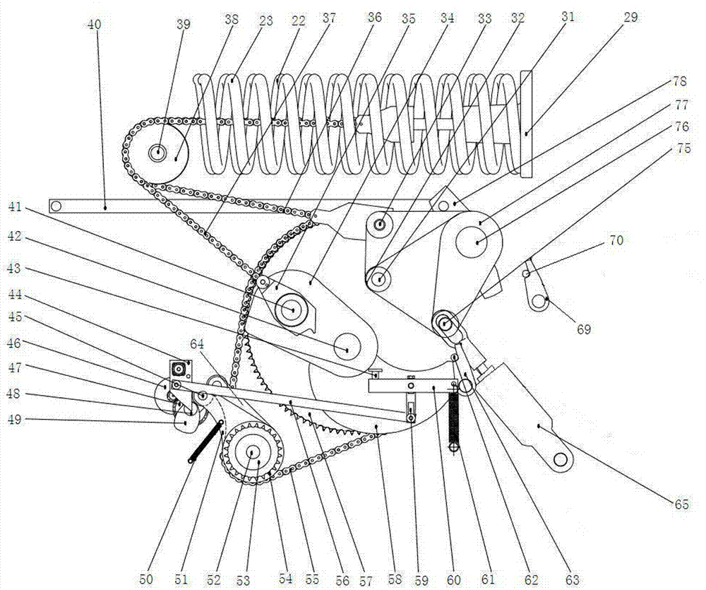
[0028] Examples of spring-operated mechanisms are Figure 1~11 Shown: including the frame, the frame includes the opening spring barrel 79, the closing spring barrel 86 and the left mounting plate 81 and the right mounting plate 80 whose lower ends are connected together by connectors, the opening spring barrel 79, the closing spring barrel 86 are side by side integrally casted, the opening spring barrel 79 and the closing spring barrel 86 are horizontally arranged, and the left and right mounting plates are also integrally cast and formed respectively, the opening spring barrel, the closing spring barrel and the left and right mounting plates are all The cast aluminum parts, the opening spring barrel and the closing spring barrel are respectively fixedly connected to the left mounting plate and the right mounting plate through a fixing structure, and the fixing structure is a bolt connection structure. The fixed structure includes a spring barrel connecting plate integrally a...


PUM


Abstract

The invention relates to a spring operating mechanism comprising a rack. A buffer and an output shaft are arranged at the rack; and the axis of the output shaft extends along the left-right direction and the output shaft is in transmission connection with a moving contact of a corresponding circuit breaker. A buffer connecting lever is assembled at the output shaft; a pin roll is arranged at the buffer connecting lever; a hinge hole is formed in a piston rod of the buffer; and the pin roll passes through the hinge hole. The hinge hole is a long hole with the length extending direction consistent with that of the piston rod. According to the provided spring operating mechanism, the initial speeds of the closing and opening of the moving contact are not influenced.

Description

technical field [0001] The invention relates to a spring operating mechanism for a circuit breaker. Background technique [0002] The operating mechanism is an important equipment in the field of high-voltage power transmission and transformation, and is an important part of the high-voltage circuit breaker. The opening and closing operations of the high-voltage circuit breaker are realized through the operating mechanism. The operating mechanism of high-voltage circuit breakers is mainly divided into two types: hydraulic operating mechanism and spring operating mechanism. The hydraulic operating mechanism has the advantages of short opening and closing time and stable performance, but it also has complex structure, high cost, and easy leakage Oil, easy to be affected by the use of the environment and other disadvantages. The spring operating mechanism has no oil leakage problem, and has the characteristics of low cost, simple structure, stable and reliable performance, and...

Claims


Application Information

Patent Timeline
Patent Type & Authority Applications(China)
IPC IPC(8): H01H3/30H01H3/32H01H3/60
CPCH01H3/30H01H3/32H01H3/60H01H3/605
Inventor 钟建英刘宇宋超宋广民朱苛娄闫广超邹高鹏王振付亚旭陈金钟王守山王亚辉许家源苏计东郭良超
Owner STATE GRID CORP OF CHINA
Features
  • R&D
  • Intellectual Property
  • Life Sciences
  • Materials
  • Tech Scout
  • Unparalleled Data Quality
  • Higher Quality Content
  • 60% Fewer Hallucinations
Learn More