Coil structure for rotary electric machine

A technology for rotating electrical machines and coils, applied in the shape/style/structure of winding conductors, etc., can solve problems such as miniaturization of difficult-to-rotate electrical machines, and achieve the effects of shortening length, reducing manufacturing man-hours, and reducing noise

Active Publication Date: 2015-01-21
HONDA MOTOR CO LTD
View PDF8 Cites 11 Cited by
  • Summary
  • Abstract
  • Description
  • Claims
  • Application Information

AI Technical Summary

Problems solved by technology

[0019] However, in the coil of the above-mentioned structure, it is difficult to further shorten the sum of the axial height of the overlapping portion on the one end side and the axia

Method used


Image

  • Coil structure for rotary electric machine
  • Coil structure for rotary electric machine
  • Coil structure for rotary electric machine

Examples


Embodiment Construction

[0067] refer to Figure 1 to Figure 11 , an embodiment of the present invention will be described.

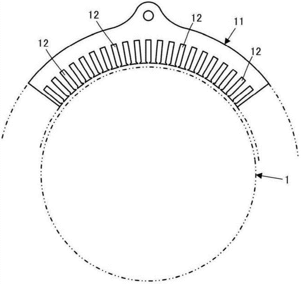
[0068] The rotating electrical machine of this embodiment includes: a substantially cylindrical stator 11 arranged around a rotor 1 ; and a magnetic flux generating coil 21 attached to the stator 11 .

[0069] Such as figure 1 As shown, a plurality of slots 12 are formed on the stator 11 along the circumferential direction of the stator 11 (direction around the axis of the stator 11 ) at regular intervals. Each slot 12 is provided so as to penetrate the stator 11 in its axial direction.

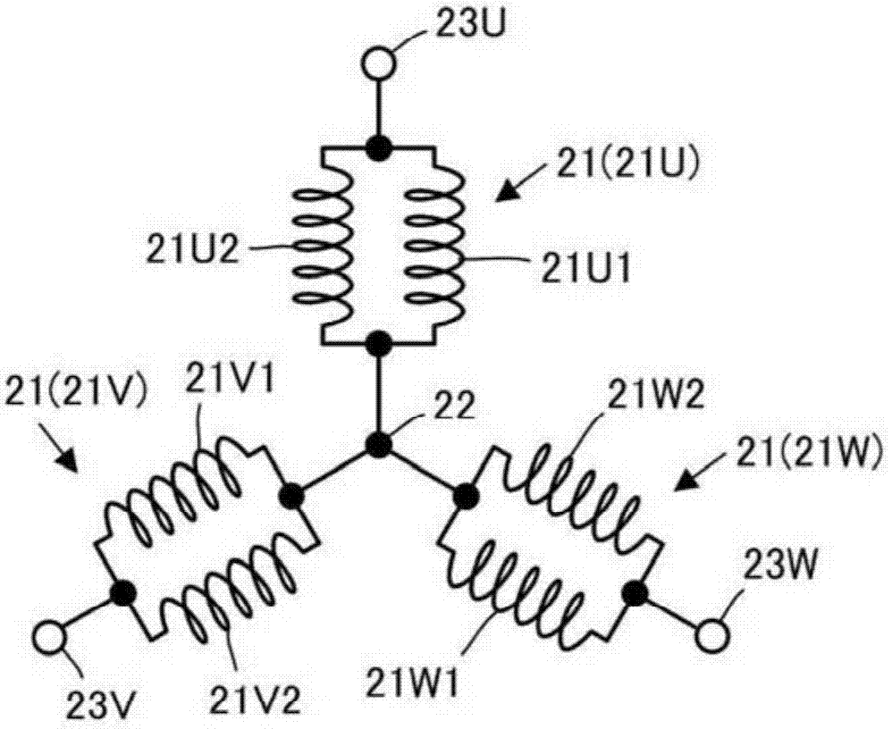
[0070] Such as figure 2 As shown, the coil 21 is constituted by three-phase coils of a U-phase coil 21U, a V-phase coil 21V, and a W-phase coil 21W. In this embodiment, the coils 21U, 21V, and 21W of the respective phases are configured by connecting two coils ( 21U1 , 21U2 ), ( 21V1 , 21V2 ), and ( 21W1 , 21W2 ) in parallel. In addition, one ends of the U-phase, V-phase, and W-phase coi...


PUM


Abstract

A coil structure for a rotary electric machine includes phase coils for magnetic flux generation. Each of the phase coils includes a plurality of first element conductors, a plurality of second element conductors, a plurality of first crossover portions, and a plurality of second crossover portions. The plurality of second element conductors are provided in a plurality of second slots among slots. The second slots are provided in a circumferential direction of a stator at a pitch of a first predetermined interval. The second slots are shifted in phase by a second predetermined interval with respect to first slots in the circumferential direction of the stator. The first predetermined interval is set to be an interval equivalent to N times a unit pitch. The second predetermined interval is set to be an interval smaller than the first predetermined interval.

Description

technical field [0001] The present invention relates to a structure of a magnetic flux generating coil mounted on a stator of a rotating electric machine. Background technique [0002] Conventionally, as a structure of a magnetic flux generating coil mounted on a stator of a rotating electric machine, structures shown in Patent Documents 1 and 2 are known. [0003] The coils shown in the above-mentioned Patent Documents 1 and 2 are coils having a structure in which a plurality of element conductors are connected in series through overlapping portions provided on one end side and the other end side in the axial direction of the stator. Insert them respectively in the slots formed on the stator of the rotating electric machine. [0004] 【Prior technical literature】 [0005] 【Patent Literature】 [0006] [Patent Document 1] Japanese Patent Laid-Open No. 2012-29370 [0007] [Patent Document 2] Specification of US Patent No. 7034428 [0008] 【Summary of Invention】 [0009] 【...

Claims


Application Information

Patent Timeline
IPC IPC(8): H02K3/28H02K3/12
CPCH02K3/28H02K3/12
Inventor 柴田匠松冈庆久
Owner HONDA MOTOR CO LTD
Why Eureka
Try Eureka