Bubble removing structure for blind hole electroplating management groove of high-density interconnected circuit board

A high-density interconnection and circuit board technology, applied in electrical components, printed circuits, printed circuit manufacturing, etc., can solve problems such as hindering the exchange of medicinal liquids, thin copper, high resistance, etc., to reduce attractiveness and ensure quality. Effect

Inactive Publication Date: 2015-01-21
TIANJIN PRINTRONICS CIRCUIT CORP
View PDF5 Cites 0 Cited by
  • Summary
  • Abstract
  • Description
  • Claims
  • Application Information

AI Technical Summary

Problems solved by technology

In practice, it is found that blind hole electroplating often has the problem of thin copper in the hole. When customers are soldering, serious performance problems such as open circuit and high resistance occur due to thermal shock, resulting in huge economic losses for customers. After technical analysis, the main reasons are: Due to the existence of the gas pipe, the tiny air bubbles in the liquid medicine enter the spray system at the same time, and then enter the blind hole, hindering the exchange of the liquid medicine in the blind hole, and finally the problem of copper thinning occurs
Some manufacturers close the gas pipe, and some manufacturers install blocking plates in the tank, but the effect is not very good

Method used


Image

  • Bubble removing structure for blind hole electroplating management groove of high-density interconnected circuit board
  • Bubble removing structure for blind hole electroplating management groove of high-density interconnected circuit board
  • Bubble removing structure for blind hole electroplating management groove of high-density interconnected circuit board

Examples


Embodiment Construction

[0016] Below in conjunction with the examples, the present invention is further described, the following examples are illustrative, not limiting, and the protection scope of the present invention cannot be limited by the following examples.

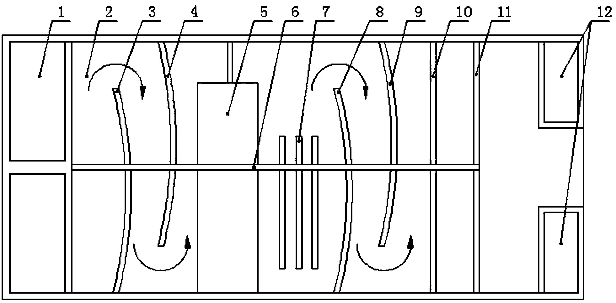
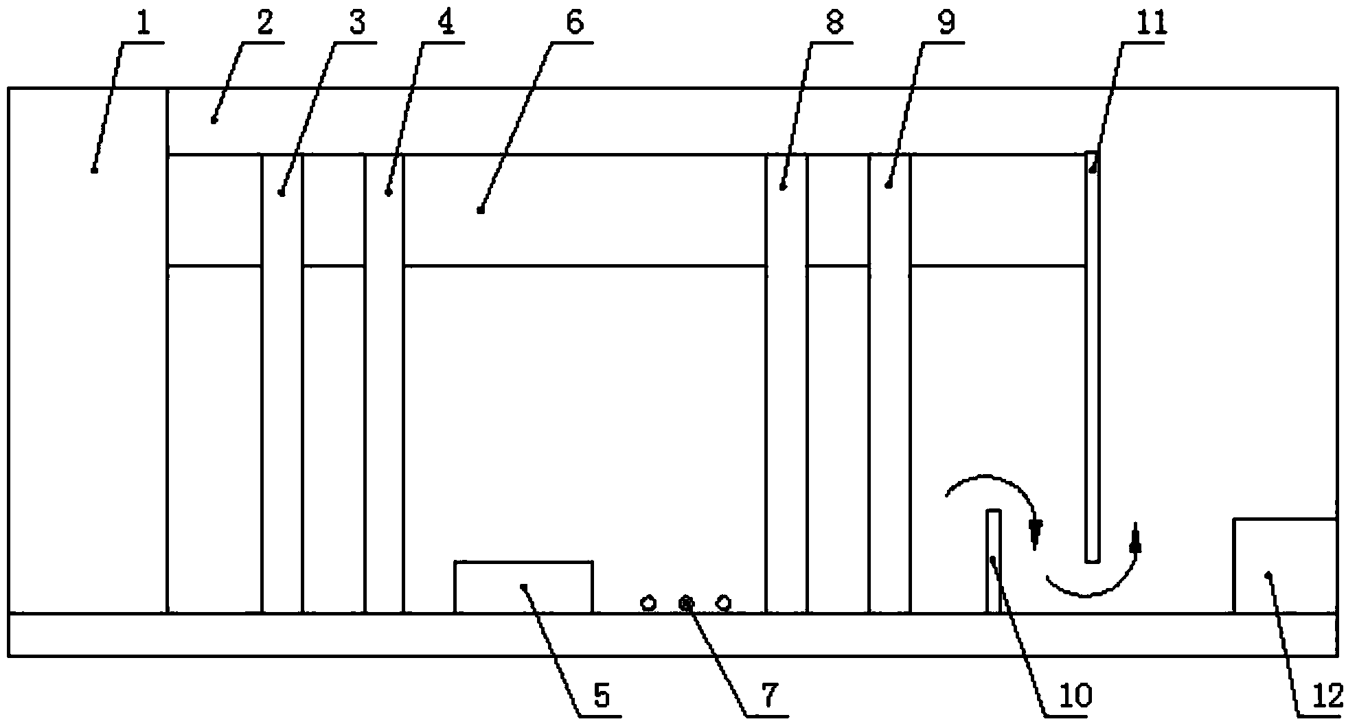
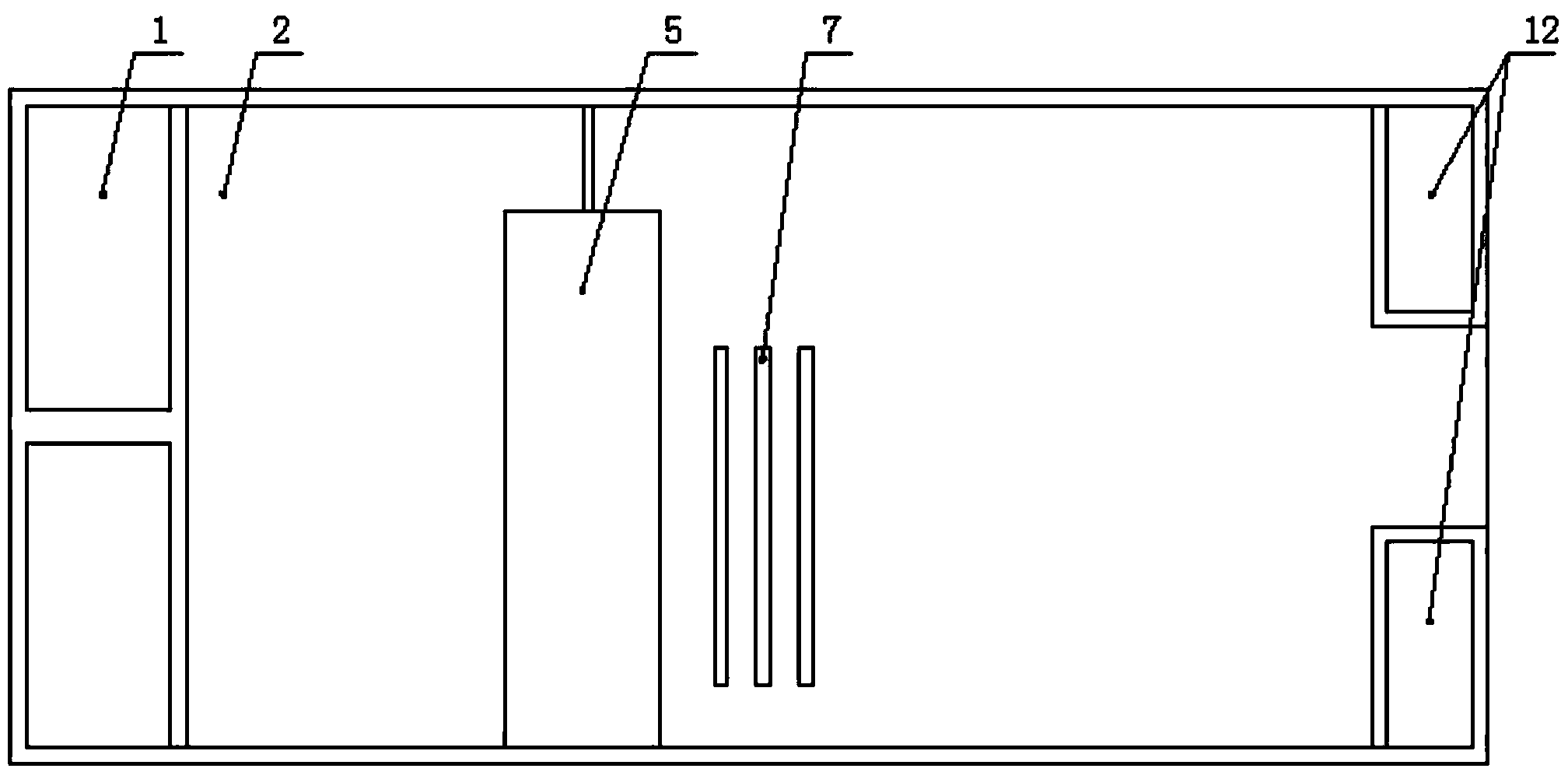
[0017] A high-density interconnect circuit board blind hole electroplating management groove bubble removal structure, such as figure 1 , 2 As shown, it includes a tank body 2, a drug inlet 1, an inflating tube 5, a heating tube 7 and a drug outlet 12. The drug inlet and the drug outlet are respectively located at two ends of the tank body, between the drug inlet and the drug outlet. The bottom of the trough between them is installed in turn with an inflating pipe and a heating pipe. The innovation of the present invention lies in that a plurality of front baffles 3 and 4 are installed on both side plates of the trough between the inflating pipe and the medicine inlet in staggered intervals. Two front baffles form a transverse serpentin...


PUM


Abstract

The invention relates to a bubble removing structure for a blind hole electroplating management groove of a high-density interconnected circuit board. According to the bubble removing structure for the blind hole electroplating management groove of the high-density interconnected circuit board, multiple front baffles are installed on two side plates on the portion, between an inflating pipe and a liquid chemical inlet, of a groove body in a staggered and spaced mode respectively, a transverse S-shaped liquid chemical channel is formed by the multiple front baffles, multiple rear baffles are installed on the two sides of the portion, between a heating pipe and a liquid chemical outlet, of the groove body in a staggered and spaced mode respectively, and another transverse S-shaped liquid chemical channel is formed by the multiple rear baffles. According to the bubble removing structure for the blind hole electroplating management groove of the high-density interconnected circuit board, the front baffles and the rear baffles are arranged in the staggered mode, liquid chemical entering from the liquid chemical inlet flows in the two S-shaped channels, the flowing distance is increased, and thus gas in the liquid chemical can be discharged completely; two vertical baffles play a role in blocking, and the attraction of a spraying pump in a spraying system to residual bubbles in liquid chemical is reduced; due to the fact that the two measures are taken, liquid chemical entering the spraying system contains no bubble, and the blind hole electroplating quality is guaranteed.

Description

technical field [0001] The invention belongs to the technical field of blind hole electroplating, in particular to a structure for removing air bubbles in a blind hole electroplating management groove of a high-density interconnected circuit board. Background technique [0002] In the manufacturing process of high-density interconnected circuit boards, the plating quality of blind holes is one of the most important performance indicators. The structure of the blind hole plating management groove involved is as follows: image 3 Shown: It includes tank body 2, drug inlet 1, gas pump 5, heating tube 7 and drug outlet 12. The drug solution enters the tank body through the drug inlet, and then flows through the gas pump and heating tube, and then flows out of the drug outlet. Flows into the sprinkler system in the main tank. In practice, it is found that blind hole electroplating often has the problem of thin copper in the hole. When customers are soldering, serious performance ...

Claims


Application Information

Patent Timeline
Patent Type & Authority Applications(China)
IPC IPC(8): H05K3/42
CPCH05K3/423H05K2203/0703
Inventor 吴云鹏
Owner TIANJIN PRINTRONICS CIRCUIT CORP
Why Eureka
Try Eureka