
Electronic module and method for manufacturing same

An electronic module and manufacturing method technology, applied in semiconductor/solid-state device manufacturing, circuits, electrical components, etc., can solve problems such as miniaturization of electronic modules that are difficult to adjust the heat sink

Active Publication Date: 2015-01-21
SHINDENGEN ELECTRIC MFG CO LTD
View PDF3 Cites 8 Cited by
  • Summary
  • Abstract
  • Description
  • Claims
  • Application Information

AI Technical Summary

Problems solved by technology

That is, conventionally, there was a problem that it was difficult to miniaturize electronic modules with heat sinks such as regulators.

Method used


Image

  • Electronic module and method for manufacturing same
  • Electronic module and method for manufacturing same
  • Electronic module and method for manufacturing same

Examples


Embodiment approach 1

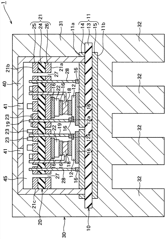
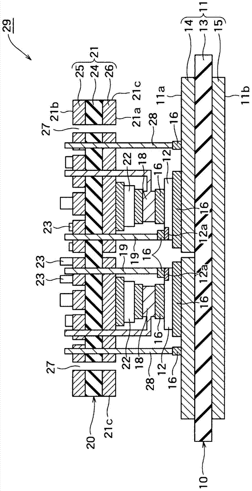
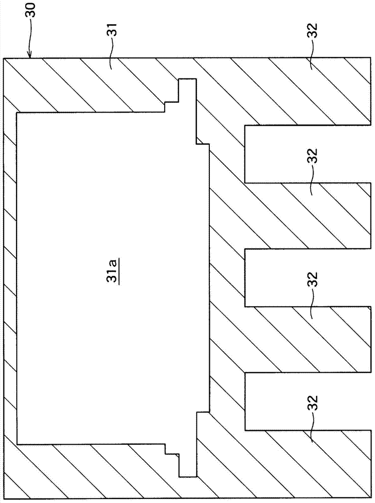
[0034] For Embodiment 1 of the present invention, refer to Figure 1 to Figure 3 Be explained. figure 1 It is a cross-sectional view of the electronic module 1 according to the first embodiment. figure 2 It is a cross-sectional view of a laminated module 29 in which two electronic modules 10 and 20 are laminated. image 3 It is a sectional view of the heat sink 30 provided with the accommodating part 31a concerning Embodiment 1. As shown in FIG.

[0035] The electronic module 1 according to Embodiment 1 includes an electronic module 10 , an electronic module 20 stacked on the electronic module 10 , and a heat sink 30 that accommodates the electronic module 10 and the electronic module 20 therein.

[0036] Such as figure 2As shown, the electronic module 10 and the electronic module 20 are laminated to form a laminated module 29 . The planar size of the substrate 21 is smaller than that of the substrate 11 . In addition, when the laminated module 29 is viewed in the thic...

Embodiment approach 2

[0075] For the second embodiment of the present invention, refer to Figure 5 Be explained. Figure 5 It is a cross-sectional view of the electronic module 1A according to the second embodiment. One of the differences between Embodiment 2 and Embodiment 1 lies in the structure of the cover. Hereinafter, Embodiment 2 will be described around this difference.

[0076] Such as Figure 5 As shown, in Embodiment 2, the cover portion 40A covers the main surface 21 b of the substrate 21 , and the space between the substrate 11 and the substrate 21 is not covered by the cover portion 40A. In addition, the outer surface of the lid portion 40A is in contact with the inner wall surface of the housing portion 31 a of the heat sink 30 .

[0077] In addition, the lid portion 40A is desirably made of a metal whose surface is insulated (for example, aluminum anodized aluminum), but may be made of an insulator.

[0078] Such as Figure 5 As shown, in the cover part 40A, the resin injecti...


PUM


Abstract

[Problem] To provide an electronic module that can be miniaturized, and a method for manufacturing the same. [Solution] An electronic module (1) provided with: an electronic module (10) having a substrate (11) that has a principal surface (11a) and a principal surface (11b), and also having an electronic element (12) mounted on the principal surface (11a); an electronic module (20) thermally connected to the electronic module (10) via connecting members (18, 19), the electronic module (20) having a substrate (21) that has a primary surface (21a) and a primary surface (21b) and is disposed so that the primary surface (21a) faces the primary surface (11a), and also having an electronic element (22) mounted on the primary surface (21a) and electrically connected to the electronic element (12) via the connecting member (18), and an electronic element (23) mounted on the primary face (21b) and electrically connected to the electronic element (12) via the connecting member (19)that passes through the substrate (21) in the thickness direction; and a heat sink (30) internally provided with a storage section (31a), the heat sink (30) storing the electronic modules (10, 20) in the storage section (31a) so that the primary surface (11b) is in contact with the inner wall surface of the storage section (31a).

Description

technical field [0001] The present invention relates to an electronic module (module) and a manufacturing method thereof, more particularly to an electronic module with a heat sink (heat sink) and a manufacturing method thereof. Background technique [0002] Conventionally, a regulator is known as an electronic module that obtains required output power from input power. Such as Figure 6 As shown, the conventional regulator 100 includes a power unit 110 , a control unit 120 and a radiator 130 . The power unit 110 performs power conversion by an electronic element 112 such as a semiconductor switching element mounted on a substrate 111 . The control unit 120 controls the power unit 110 through an electronic component 122 such as a control element mounted on a substrate 121 . The power unit 110 and the control unit 120 are electrically connected through the connection terminal 113 . The heat sink 130 has a base plate 131 and a plurality of fins 132 vertically provided under...

Claims


Application Information

Patent Timeline
Patent Type & Authority Applications(China)
IPC IPC(8): H01L23/36H01L23/40H01L25/07H01L25/18
CPCH01L23/40H01L23/36H01L25/18H01L25/07H01L23/3675H01L23/3735H01L23/49844H01L23/5385H01L23/3737H01L23/42H01L23/051H01L21/50H01L24/33H01L25/071H01L25/165H01L2924/13055H01L2924/13091H01L2224/32013H01L2224/1318H01L2224/3303H01L23/48H01L24/13H01L24/16H01L24/29H01L24/73H01L24/81H01L24/92H01L2224/13016H01L2224/13082H01L2224/13147H01L2224/13294H01L2224/133H01L2224/16237H01L2224/293H01L2224/32014H01L2224/32227H01L2224/32245H01L2224/33181H01L2224/73203H01L2224/73253H01L2224/73265H01L2224/81447H01L2224/81815H01L2224/83447H01L2224/8348H01L2224/83815H01L2224/9211H01L2224/9221H01L2224/92247H01L2924/16152H01L2924/1679H01L2224/29294H01L2924/1611H01L2924/16724H01L24/32H01L24/83H01L2924/00H01L2924/00014H01L2224/81H01L2224/83H01L2924/00012H01L2924/01042H01L2924/01074H01L21/4817H01L21/565H01L23/055H01L23/16H01L23/3672H01L23/49827H01L23/49838H01L23/49866H01L25/0657H01L25/50H01L2224/32225H01L2225/06548H01L2225/06555H01L2225/06572H01L2225/06582H01L2225/06589
Inventor 池田康亮
Owner SHINDENGEN ELECTRIC MFG CO LTD
Learn More