
A synchronizer gear sleeve deburring machine and its use method

A deburring machine and synchronizer technology, applied in the field of synchronizer processing, can solve the problems of burr hypertrophy, affecting the roughness of the tooth surface, not considering burrs, etc., achieving fast pressing and loosening, improving assembly qualification rate, and burr removal. thorough effect

Active Publication Date: 2017-06-23
SHAANXI FAST AUTO DRIVE GROUP CO LTD
View PDF6 Cites 0 Cited by
  • Summary
  • Abstract
  • Description
  • Claims
  • Application Information

AI Technical Summary

Problems solved by technology

Among them, the burrs on the tooth-missing surface and the spline tooth surface near the V-shaped groove are mainly removed by manual filing. Internal spline teeth are removed tooth by tooth in the direction of the internal spline, which is inefficient and easy to scratch the tooth surface of the internal spline, affecting the roughness of the tooth surface, and repeated manual handling will cause parts to bump; manual processing has a faster cycle time of 40 seconds / piece
[0003] To solve the problem of burrs, Germany has equipped an automatic deburring mechanism in the existing special machine tools for compound processing of gear sleeves. However, because Germany adopts advanced cycloidal theory to process grooves, the burrs generated by gear sleeves are small and thin, and can be easily removed. ;Due to the different processing methods of domestic gear sleeves (using machining centers with forming milling cutters), the burrs are hypertrophic, so that the German deburring technology cannot be directly adopted; in addition, German machine tools do not consider the burrs on the missing teeth of the gear sleeve splines. Requires manual file removal

Method used


Image

  • A synchronizer gear sleeve deburring machine and its use method
  • A synchronizer gear sleeve deburring machine and its use method
  • A synchronizer gear sleeve deburring machine and its use method

Examples


Embodiment Construction

[0036] Below in conjunction with accompanying drawing, the present invention is described in further detail:

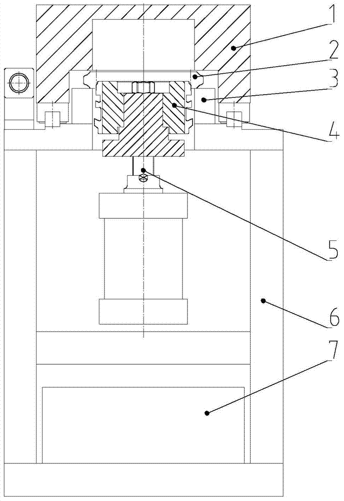
[0037] refer to figure 1 , the present invention comprises machine tool body 6, and the cooling box 7 that has cutting fluid, hydraulic cylinder 5, knife shim, push knife 4, workpiece 2 and horizontal slide plate 1 are installed successively in machine tool body 6 from bottom to top, wherein push knife 4 It is cylindrical, and the workpiece 2 is circular and has an internal spline structure; the push knife 4 is provided with an I-shaped through hole connecting the piston rod of the hydraulic cylinder 5 along the axial direction, and the push knife 4 and the hydraulic cylinder 5 are provided. Knife pad, push knife 4 is equipped with supporting part 3, which is used to position and support workpiece 2; workpiece 2 is partly sleeved on push knife 4; slide plate 1 is installed on machine tool body 6 horizontally through guide rail, and slide plate 1 can be horizontally ...


PUM


Abstract

The invention relates to a deburring machine for a synchronizer gear sleeve and a method for using the same. It comprises a machine tool body capable of fixing a ring-shaped synchronizer gear sleeve workpiece. The push knife moves to remove the burr of the inner spline of the workpiece and moves downward to return to its original position. The push knife includes an outer spline that cooperates with the inner spline of the workpiece; the lower end of the workpiece is coaxially sleeved on the upper end of the push knife with a gap between them There are gaps. In the present invention, the workpiece is fixed on the machine tool body, the push knife is socketed on the lower side of the workpiece, and the external splines are arranged to cooperate with the internal splines of the workpiece, and the deburring method of pressing up and down is adopted to effectively remove all burrs; only Through the upward movement of the push knife, the burr is removed at one time, and the efficiency is extremely high. There is a gap between the outer spline of the push knife and the inner spline of the workpiece, so that the push knife will not damage the surface of the inner spline of the workpiece and will not affect the roughness of the tooth surface. The degree of deburring will not be missed; at the same time, the transfer of parts is reduced and the bumping of parts is prevented.

Description

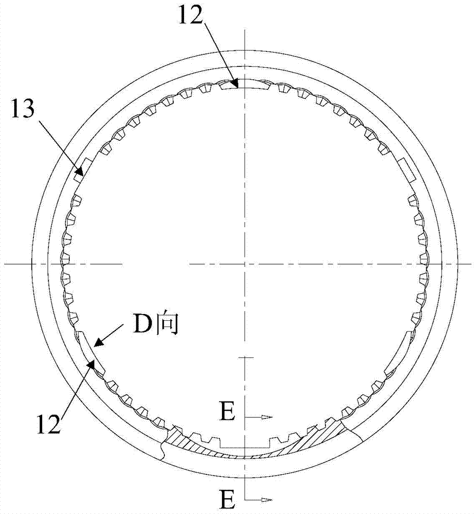
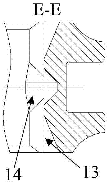
technical field [0001] The invention belongs to the field of synchronizer processing, and in particular relates to a synchronizer gear sleeve deburring machine and a use method thereof. Background technique [0002] At present, the splines of the existing synchronizer gear sleeves are processed with connected teeth, missing teeth, V-shaped grooves and other small teeth. In China, forming milling cutters are used to process 90° V-shaped grooves on the original internal splines. and 25° chute, etc., resulting in serious burr flanging, see Figure 2 to Figure 4 , the spline of the synchronizer gear sleeve is the internal spline of the workpiece 2, including three evenly distributed teeth 12 along the circumferential direction of the workpiece 2, three groups of missing teeth 13 (with 25° inclined grooves), three V-shaped grooves 14 and Several small teeth, the burr is located on the tooth surface of the connecting tooth 12, the missing tooth 13, the V-shaped groove 14 and the s...

Claims


Application Information

Patent Timeline
Patent Type & Authority Patents(China)
IPC IPC(8): B23D79/00
Inventor 刘亚军周旗杨平刘立明姬汶辰
Owner SHAANXI FAST AUTO DRIVE GROUP CO LTD
Learn More