
A traction device that guides copper tubes through the fins of the condenser

A traction device and condenser technology, applied in metal processing, metal processing equipment, manufacturing tools, etc., can solve the problems that it is difficult to ensure that the copper pipes pass through sequentially, mass production cannot be realized, and the guiding process is prone to deviation. Achieve the effects of reducing product scrap rate and labor costs, accurate insertion, and avoiding collision deformation

Active Publication Date: 2017-02-15
广州绅特模具制造有限公司
View PDF6 Cites 0 Cited by
  • Summary
  • Abstract
  • Description
  • Claims
  • Application Information

AI Technical Summary

Problems solved by technology

Since the fin is a sheet-like structure made of aluminum foil with a thickness of about 0.1mm, its material is very soft, and the thickness of the copper tube is also very thin. When the U-shaped copper tube passes through the stacked fins, it is very difficult. It is difficult to ensure that the copper tubes can pass through all the fins in turn, which will easily cause the fin holes and copper tubes to deform, and at the same time, it is easy to shift during the guiding process, resulting in the scrapping of the entire condenser and the consumption of materials
Moreover, it takes a long time to thread the pipe, the production efficiency is low, and it is impossible to realize mass production

Method used


Image

  • A traction device that guides copper tubes through the fins of the condenser
  • A traction device that guides copper tubes through the fins of the condenser
  • A traction device that guides copper tubes through the fins of the condenser

Examples


Embodiment Construction

[0030] The specific embodiments of the present invention will be further described below in conjunction with the accompanying drawings.

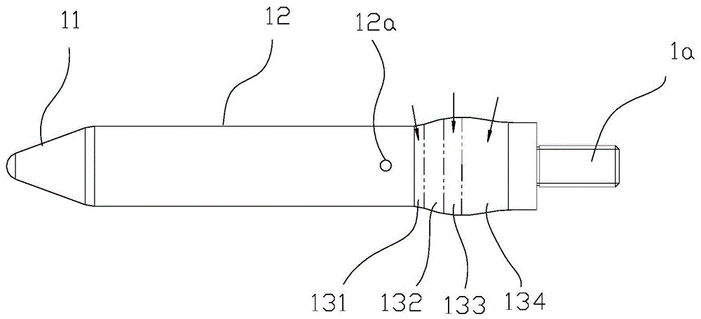
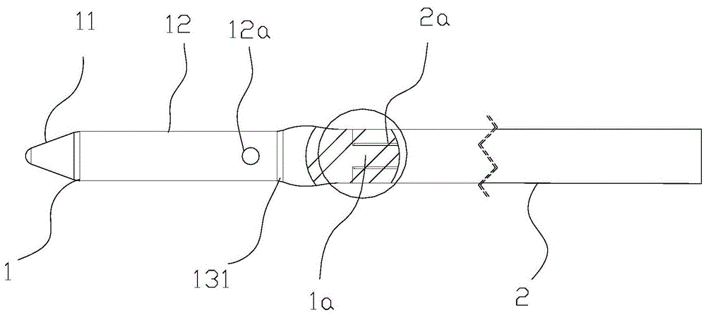
[0031] Refer to attached figure 1 To attach figure 2 As shown, a draw rod for guiding copper tubes through the fins of the condenser includes a detachably connected draw head 1 and a rod body 2, and the end of the draw head 1 is provided with a convex buckle 1a extending along its length direction, so The front end of the rod body 2 is provided with a groove 2a that engages with the convex buckle 1, and the convex buckle 1a is spirally connected with the groove 2a. The pulling head is provided with a jack 12a that can be inserted into a screwdriver. Through the jack 12a Install and connect or disassemble the traction head and rod body. The front end of the pulling head 1 is a pointed insertion part 11, the middle end is a linear holding part 12, the rear end includes a shielding part 132 protruding upwards from front to back, and a shield...


PUM


Abstract

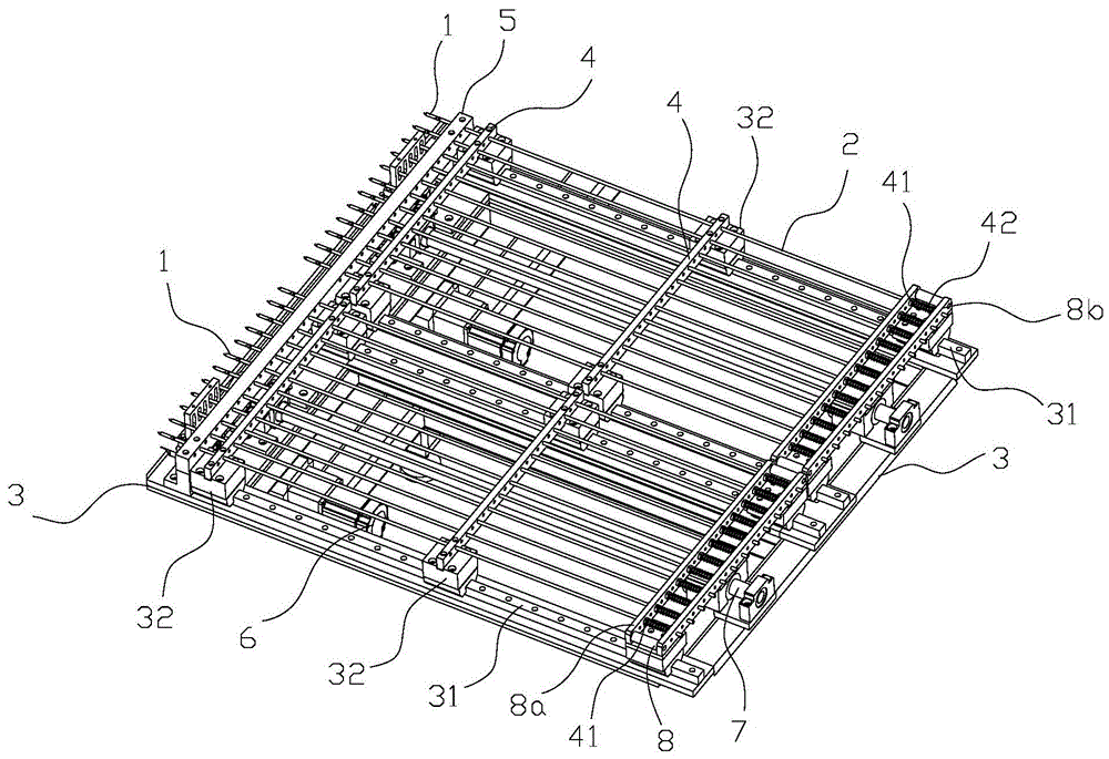
The invention discloses a traction rod and a traction device for guiding copper pipes to penetrate through condenser fins. The traction rod comprises a traction head and a rod body, wherein a pointy inserting portion is arranged at the front end of the traction head, a straight line-shaped retaining portion is arranged at the middle end of the traction head, a shielding portion bulged upwards from front to back, an arranging portion continuously bulged from the shielding portion to the highest position and a buffering portion transiting downwards from the rear of the arranging portion are arranged at the rear end of the traction head, and a joint portion is arranged between the retaining portion and the shielding portion. The traction device comprises a plurality of traction rods arranged in parallel, a support seat, sliding rails, driving mechanisms and guiding mechanisms, wherein the driving mechanisms drive the guiding mechanisms at the rear ends of the corresponding traction rods so as to drive the corresponding traction rods to move back and forth. While the traction rods retreat from the holes of the fins, the copper pipes are synchronously guided into the holes of the fins. According to the traction rod and the traction device, the structure is reasonable, the degree of automation is high, and the cost is low; the copper pipes can be safely, accurately and quickly inserted in the condenser fins, so that the pipe penetrating efficiency and precision are high, the product rejection rate and manpower cost are greatly reduced, and the traction rod and the traction device can be used in mass industrial production.

Description

technical field [0001] The invention belongs to the field of air-conditioning condenser processing equipment, and in particular relates to a draw bar and a draw device for guiding copper pipes through condenser fins. Background technique [0002] The air conditioner condenser includes a fin set and U-shaped copper tubes passing through the fin set, and passing copper tubes on the condenser fins is an important link in the preparation of the air conditioner. The traditional main process of threading tubes on fins is to rely on special material receivers to automatically and neatly stack them into fin layers, use high-speed punching machines to automatically punch fin holes for copper tubes to pass through on the fins, and then rely on workers to manually insert them into fin layers. The U-shaped copper tube penetrates into the fin channel formed by aligning the fin holes of multiple rows of fins. Since the fin is a sheet-like structure made of aluminum foil with a thickness ...

Claims


Application Information

Patent Timeline
Patent Type & Authority Patents(China)
IPC IPC(8): B23P19/00
CPCB23P19/04
Inventor 徐桂明
Owner 广州绅特模具制造有限公司
Learn More