A simple cutting machine

A cutting machine, a simple technology, applied in the direction of circular saws, wood processing equipment, sawing components, etc., can solve the problems of inconvenient disassembly, large contact area, short service life, etc., to achieve convenient cooperation, clean working environment, The effect of long service life

Inactive Publication Date: 2016-04-06
ZHEJIANG ANJI ANFENG FURNITURE
View PDF5 Cites 0 Cited by
  • Summary
  • Abstract
  • Description
  • Claims
  • Application Information

AI Technical Summary

Problems solved by technology

[0002] Existing cutting machines come in a variety of forms, including high-precision and simple ones. As processing equipment for small factories of handmade products, large quantities of cut-to-length cutting boards are not needed, and only manual ones with high mobility are required. Convenient tools are enough, and the size of the equipment and the cost of the equipment must also be considered. Generally, the simplest ones are selected and directly pushed manually. The traditional simple cutting machine uses rails and frame groove rails at the bottom. Once one of the two parts of the guide rail is damaged, it will basically affect the other part, making the guide rail unusable. The contact area between the two is large, the mutual influence is large, the disassembly is also very inconvenient, the friction is large, it is easy to get stuck, and the service life is short , and when the existing push table is sawed, the board needs to be pressed by manual hands to prevent the board from deviation and rotation during the sawing process. Bigger security risk

Method used


Image

  • A simple cutting machine
  • A simple cutting machine
  • A simple cutting machine

Examples


Embodiment 1

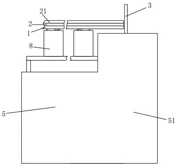
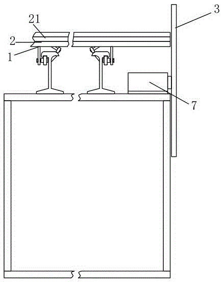
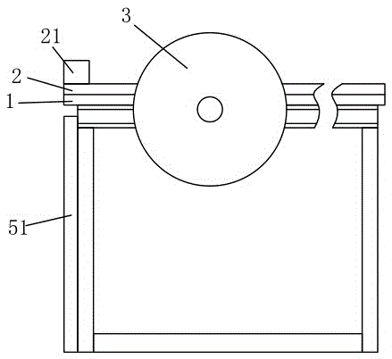
[0045]A simple board cutting machine, including a frame, at least two symmetrically arranged guide rails arranged on the top of the frame, a push platform mounted on the two guide rails and moving back and forth along the guide rails and having rolling parts that cooperate with the guide rails, and a disk surface and A circular saw 3 parallel to the length direction of the guide rail, the push table frame includes a push frame 1 erected on the guide rail and a push table plate 2 detachably arranged on the push frame, the upper surface of the push table plate is provided with a The positioning baffle 21 provided in the length direction of the guide rail and the limit block 22 that can move back and forth along the length direction of the guide rail for cooperating with the positioning baffle to clamp objects, the guide rail includes a bottom plate, a T-shaped frame rail arranged on the bottom plate, The frame rail includes a support bar 41 arranged on the bottom plate and a top ...

Embodiment 2

[0053] The difference from the above-mentioned embodiment is that the middle part of the wheel surface of the upper roller and the lower roller is provided with an auxiliary pulley cavity 64 formed in a concave shape.

Embodiment 3

[0055] The difference from the above-mentioned embodiment is that the middle part of the wheel surface of the upper roller and the lower roller is provided with an auxiliary pulley cavity 64 formed in a concave shape. The inclined rail surface and the bottom rail surface are provided with a roller limiting protrusion 65 that cooperates with the auxiliary pulley cavity.

[0056] When using, the limit block is pulled apart, the board to be sawed leans against the positioning baffle, and then the limit block is moved to cooperate with the positioning baffle to clamp the board to be sawed, the bolt is tightened, the limit block is fixed, and the push table is pushed to saw plate.

[0057] A positioning baffle for leaning against the board is set on the push table, and a limit block is provided to clamp the board between the positioning baffle and the limit block, so as to ensure that the board does not need to be pressed manually when it is sawed. It will not rotate even if it st...


PUM


Abstract

The invention belongs to the field of a plate cutting machine, and particularly relates to a simple plate cutting machine with the advantages that simplicity is realized, the dismounting and the mounting are convenient, and the operation is simple. The simple plate cutting machine comprises a machine frame, a guide rail, a pushing table frame and a circular disc saw, wherein the pushing table frame comprises a pushing frame and a pushing table plate, the upper surface of the pushing table plate is provided with a positioning baffle plate and a position limiting block, the guide rail comprises a bottom plate and a frame rail, the frame rail is arranged on the bottom plate, the cross section of the frame rail is in a T shape, the frame rail comprises a support strip and a top rail strip, an inclined rail surface is arranged at one side of the upper surface of the top rail strip, the lower surface, positioned at one side opposite to the inclined rail surface in the lower surface positioned at the two sides of the support strip, of the top rail strip is a bottom rail surface, a rolling component comprises an upper rolling wheel and a lower rolling wheel, the plate is fixedly clamped on the pushing table plate through the matching of the positioning baffle plate and the position limiting block, then, the whole pushing frame is pushed, the pushing frame is erected on the guide rail through an upper rolling wheel frame pressed on the inclined rail surface, and is then matched with the lower rolling wheel buckled on the bottom rail surface, so that the whole pushing frame is positioned and can only slide along the guide rail. The matching is convenient, the contact area of the rolling wheels and the guide rail is small, the friction force is small, and the operation and the control are free.

Description

technical field [0001] The invention belongs to the field of board cutting machines, and in particular relates to a simple board cutting machine which is simple, easy to assemble and disassemble, and easy to operate. Background technique [0002] Existing cutting machines come in a variety of forms, including high-precision and simple ones. As processing equipment for small factories of handmade products, large quantities of cut-to-length cutting boards are not needed, and only manual ones with high mobility are required. Convenient tools are enough, and the size of the equipment and the cost of the equipment must also be considered. Generally, the simplest ones are selected and directly pushed manually. The traditional simple cutting machine uses rails and frame groove rails at the bottom. Once one of the two parts of the guide rail is damaged, it will basically affect the other part, making the guide rail unusable. The contact area between the two is large, the mutual infl...

Claims


Application Information

Patent Timeline
Patent Type & Authority Patents(China)
IPC IPC(8): B27B5/06B27B29/00B27B29/02B27G19/02
CPCB27B5/06B27B29/00B27B29/02B27G19/02
Inventor 胡月宝
Owner ZHEJIANG ANJI ANFENG FURNITURE
Why Eureka
Try Eureka