
Engineering machine operation target positioning method and system

A technology for construction machinery and target positioning, applied in cranes, transportation and packaging, load hanging components, etc., can solve problems such as visual errors, tipping accidents, and low wireless positioning accuracy of target points, avoid errors and risks, improve The effect of positioning accuracy

Active Publication Date: 2015-01-28
XUZHOU HEAVY MASCH CO LTD
View PDF6 Cites 20 Cited by
  • Summary
  • Abstract
  • Description
  • Claims
  • Application Information

AI Technical Summary

Problems solved by technology
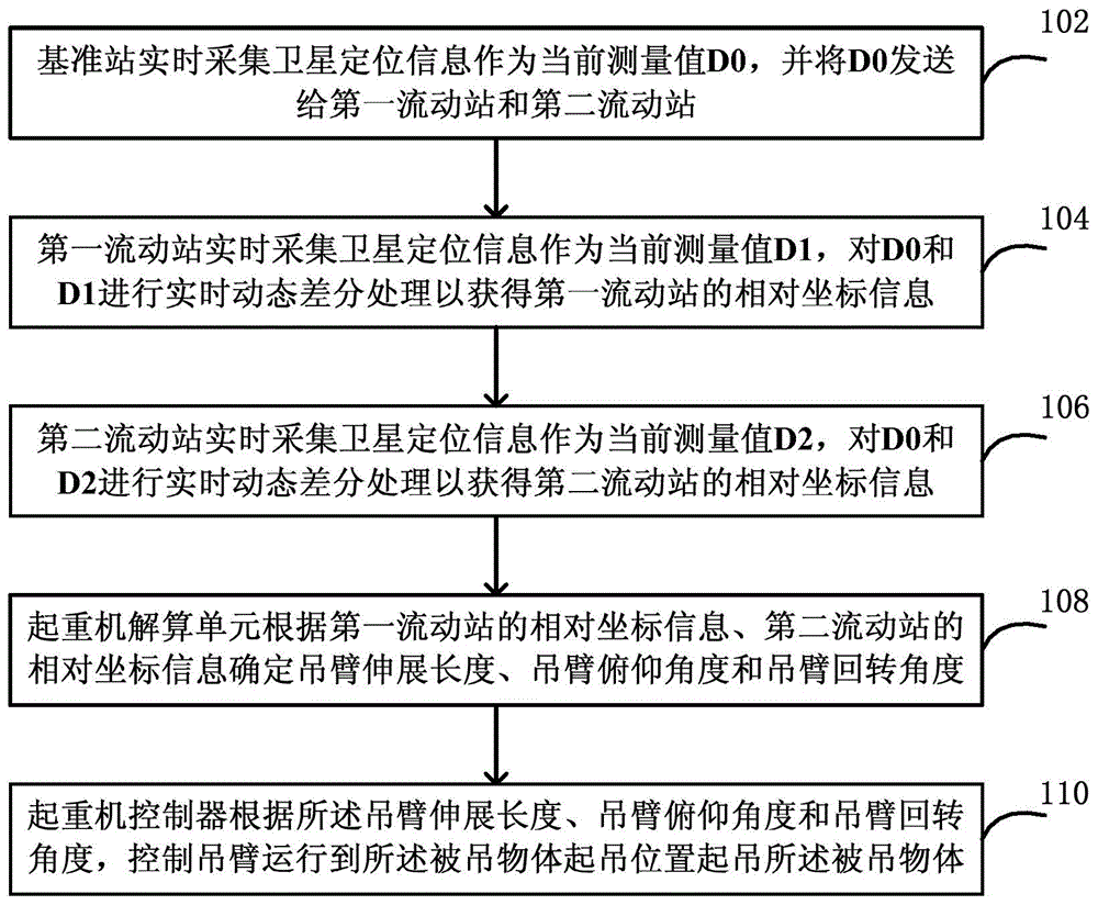
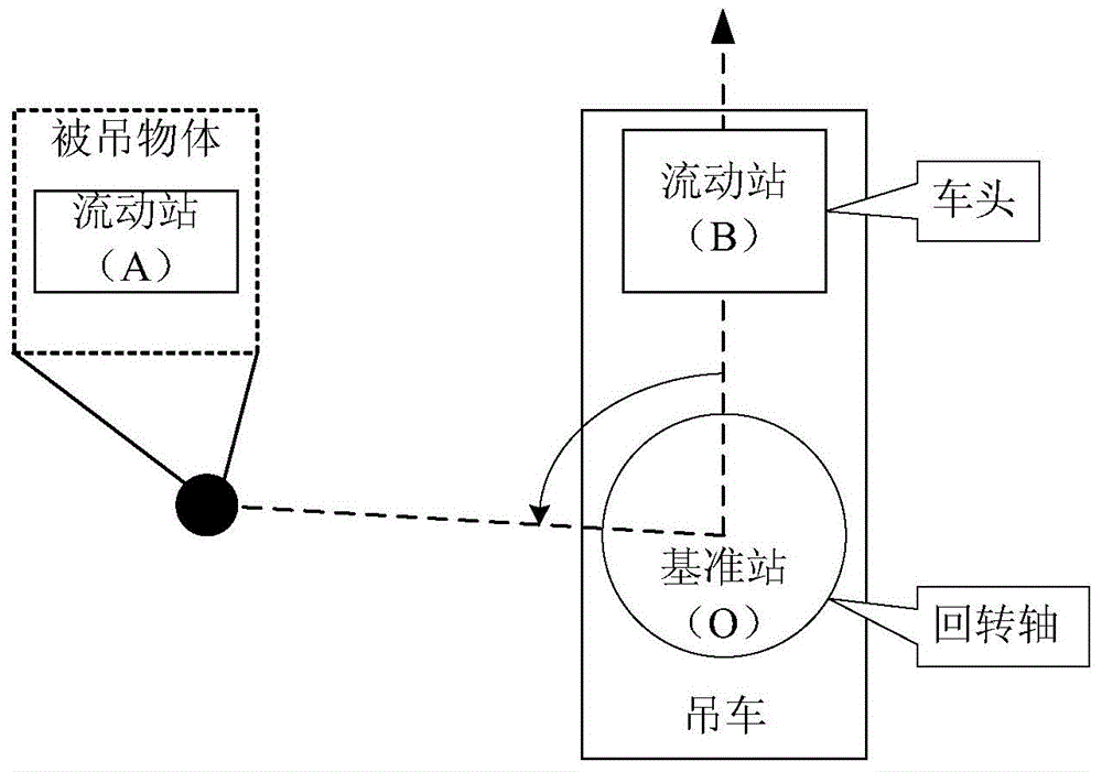
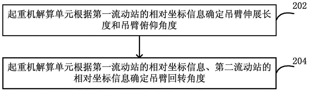
[0005] First, the wireless positioning accuracy of the target point is low
Since the high-precision wireless positioning is not open, only civilian pseudo codes are available, and the positioning accuracy of the target point is about 10 meters. When calculating the extension length of the boom and the pitch angle of the boom, the error with the actual size is too large, and it is impossible to accurately judge the hoisted the exact location of the object
If there is a deviation between the hoisted object and the crane hook in the vertical direction, the phenomenon of "slanted pull" will occur, causing damage to the crane, or even a tipping accident.
[0006] Second, the execution action of the boom is not clear
When hoisting at a long distance or working over a certain obstacle, due to the error of the operator's vision, it is impossible to accurately determine the exact position of the object being hoisted
The lifting height and lifting angle are all judged by visual inspection and experience to increase the risk

Method used


Image

  • Engineering machine operation target positioning method and system
  • Engineering machine operation target positioning method and system
  • Engineering machine operation target positioning method and system

Examples


Embodiment Construction

[0060] The following will clearly and completely describe the technical solutions in the embodiments of the present invention with reference to the accompanying drawings in the embodiments of the present invention. Obviously, the described embodiments are only some, not all, embodiments of the present invention. The following description of at least one exemplary embodiment is merely illustrative in nature and in no way taken as limiting the invention, its application or uses. Based on the embodiments of the present invention, all other embodiments obtained by persons of ordinary skill in the art without creative efforts fall within the protection scope of the present invention.

[0061] The relative arrangements of components and steps, numerical expressions and numerical values ​​set forth in these embodiments do not limit the scope of the present invention unless specifically stated otherwise.

[0062] At the same time, it should be understood that, for the convenience of d...


PUM


Abstract

The invention discloses an engineering machine operation target positioning method and system. The method comprises the following steps: (1) a reference station collects the satellite positioning information in real time as the current measured value D0, and then sends the D0 to a first moving station and a second moving station; (2) the first moving station and the second moving station individually collects the satellite positioning information in real time as the current measured value D1 and D2, and then a realtime dynamic differential treatment is carried out on between D0 and D1 and between D0 and D2 respectively so as to obtain the relative coordinate information of the first moving station and the second moving station; (3) a crane calculation unit determines the extend length, pitch angle, and rotation angle of a lifting arm according to the relative coordinate information of the first moving station and the second moving station; (4) finally the crane controls the lifting arm to move to the lifting position of an object to be lifted and lift the object according to the calculated extend length, pitch angle, and rotation angle of the lifting arm. The provided method and system can largely improve the precision of positioning on operation target, moreover the lifting arm is automatically traced, and the error and risk brought by eyeballing are avoided.

Description

technical field [0001] The invention relates to the field of construction machinery, in particular to a method and system for positioning a construction machinery operation target. Background technique [0002] During the construction operation of the crane, especially when it is hoisted at a long distance or when it is over a certain obstacle, due to the error of the operator's vision, it is impossible to accurately judge the exact position of the object being hoisted. If there is a deviation between the hoisted object and the crane hook in the vertical direction, the phenomenon of "slanted pull" will occur, causing damage to the crane, or even a tipping accident. [0003] At present, the lifting of large heavy objects often requires careful on-site investigation and calculation. Estimate the working conditions such as the extension length of the boom and the pitch angle of the boom in advance. Moreover, at the job site, it is necessary to command and dispatch the site pe...

Claims


Application Information

Patent Timeline
IPC IPC(8): B66C13/48B66C13/46B66C15/00
CPCB66C13/46B66C13/48B66C23/88B66C2700/082
Inventor 单增海朱长建赵忠祥李权朱冒峰
Owner XUZHOU HEAVY MASCH CO LTD
Features
  • Generate Ideas
  • Intellectual Property
  • Life Sciences
  • Materials
  • Tech Scout
  • Unparalleled Data Quality
  • Higher Quality Content
  • 60% Fewer Hallucinations
Learn More