
Solar multifunctional wall

A multi-functional, solar energy technology, applied in solar thermal power generation, solar thermal devices, walls, etc., can solve problems such as single function, achieve the effect of improving indoor environment, reducing waste of resources and protecting the environment

Active Publication Date: 2015-01-28
UNIV OF SCI & TECH OF CHINA
View PDF5 Cites 13 Cited by
  • Summary
  • Abstract
  • Description
  • Claims
  • Application Information

AI Technical Summary

Problems solved by technology

[0004] In order to solve the shortcoming of the single function of the traditional Trombe wall, the present invention proposes a solar multifunctional wall that can simultaneously meet the needs of heating and removing aldehydes in winter and dehumidifying and removing aldehydes in summer

Method used


Image

  • Solar multifunctional wall
  • Solar multifunctional wall
  • Solar multifunctional wall

Examples


Embodiment 1

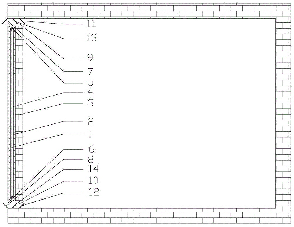
[0026] A solar multifunctional wall, comprising glass 1, crawler-type silica gel 2, wall body 3, air channel 4, vents 5, 6, 9, 10, baffles 7, 8, 11, 12, 13, 14.

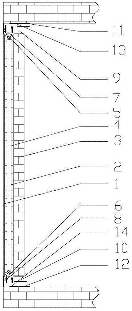
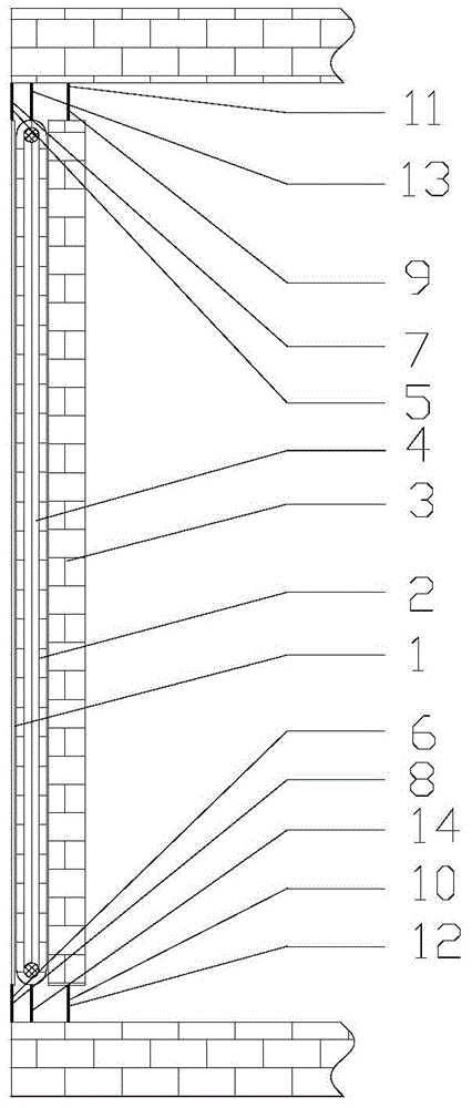
[0027] The crawler silicone rubber 2 is located in the air channel 4 between the glass 1 and the wall 3 . An outdoor upper vent 5 and an outdoor lower vent 6 are respectively opened on the upper and lower parts of the glass 1 side, and an indoor upper vent 7 and an indoor lower vent 8 are respectively opened on the upper and lower parts of the wall 3, and each vent is provided Wooden baffles 7, 8, 11, 12 are arranged, and an upper baffle 13 of an air flow channel and a lower baffle 14 of an air flow channel are respectively arranged directly above and directly below the crawler-type silica gel 2 runners.

[0028] The crawler-type silica gel 2 is prepared by mixing silica sol and nano-titanium dioxide, which can improve the adsorption of water vapor on the silica gel, and the water vapor can promote the degradation of...

Embodiment 2

[0032] Such as image 3 As shown, at night in winter, all baffles are closed, so that all vents are closed, and the runners of the crawler-type silica gel 2 do not rotate, reducing the heat lost from the room to the outside, and at the same time, the heat stored in the wall 3 during the day The heat is slowly transferred into the room by heat conduction for heating.

Embodiment 3

[0034] Such as Figure 4 As shown, during the daytime in summer, open the indoor and outdoor upper and lower baffles 11, 12 and 7, 8, make the indoor and outdoor upper and lower vents 9, 10 and 5, 6 in the opening state, and close the upper and lower air passages simultaneously. The lower baffles 13 and 14, the crawler-type silicone runners rotate upwards, and the air flow channel is divided into inner and outer sides, wherein the inner side is a dehumidification area, and the outer side is a regeneration area. The silica gel in the regeneration area absorbs solar radiation, heats the silica gel and heats the air outside the air flow channel at the same time, so that the moisture adsorbed by the silica gel is vaporized, and the air with a lower temperature at the outdoor bottom flows into the air flow channel 4 from the lower outdoor vent 6 due to thermosiphon effect The outside, and exhaust to the atmosphere through the outdoor upper vent 5. With the slow rotation of the cra...


PUM


Abstract

The invention discloses a solar multifunctional wall, relates to application of a solar heat collection, dehumidification and air purification technology and belongs to an energy utilization technology and the field of indoor air purification. The solar multifunctional wall is capable of solving the problems that a traditional Trombe wall is single in function, is only capable of heating or ventilation and cannot make full use of absorbed solar heat in summer. The solar multifunctional wall is capable of heating and removing aldehyde in a room in winter and dehumidifying and removing aldehyde in the room in summer. A crawler-type silica gel rotating wheel is prepared by mixing silica sol with nano titanium dioxide; the surface of the solar multifunctional wall is provided with an alveolate porous passage; opening and closing of a baffle and rotation of the rotating wheel are controlled according to different climatic environments, formaldehyde removal and indoor air purification can be achieved on the basis of heating or dehumidifying dry air.

Description

technical field [0001] The invention relates to the application of solar heat collection, dehumidification and air purification technologies, belongs to the field of energy utilization technology and indoor air purification, and specifically relates to a solar multifunctional wall. Background technique [0002] Scholars at home and abroad have made nearly half a century of research progress on Trombe wall technology. It was named after the French professor F.Trombe who first proposed this concept in 1966. The Trombe wall absorbs the solar radiation passing through the glass cover on the thermal storage wall with blackened outer surface. The solar radiation absorbed by the heat collecting wall is transmitted to the room through two ways: one is to transfer heat into the room through the heat conduction of the wall; the other is to heat the air in the air passage between the transparent glass cover plate and the heat collecting and storing wall. , Through the thermosiphon eff...

Claims


Application Information

Patent Timeline
IPC IPC(8): E04B2/00E04B1/64F24J2/00
CPCY02E10/40
Inventor 何伟洪晓强胡中亭吕松余本东李念思季杰
Owner UNIV OF SCI & TECH OF CHINA
Learn More