
Centering anti-eccentric anti-waxing sucker-rod coupling

A sucker rod coupling and sucker rod technology, applied in drill pipes, cleaning appliances, drilling equipment, etc., can solve the problems of reducing the flow area, damage to sucker rods, occupation, etc., to reduce resistance, prevent The effect of waxing

Inactive Publication Date: 2015-01-28
王福成
View PDF7 Cites 0 Cited by
  • Summary
  • Abstract
  • Description
  • Claims
  • Application Information

AI Technical Summary

Problems solved by technology

[0002] There are many reasons for the eccentric wear of the sucker rod and the tubing. In order to solve this problem, a centralizer has been developed, but the space between the sucker rod and the tubing is limited. This limited space is where the well fluid rises from the bottom of the well to the surface. The centralizer is working in this space. The centralizer occupies this limited space, which reduces the flow area and reduces the oil well production. At the same time, the centralizer works in the flowing well fluid and produces Resistance, this resistance increases the load of the sucker rod, causing damage to the sucker rod, and at the same time increases the power consumption and increases the mining cost. The current centralizer does not solve this problem. The hoop did not solve this problem either. The casting type sucker rod centralizer was the first to raise this problem. The application number is 2013105178078. It was proposed to ensure that the flow area between the sucker rod and the oil pipe is correct, but it did not follow the principle of fluid mechanics. The design of the centralizer does not reduce the resistance caused by the centralizer to the well fluid
Does not reduce the frictional resistance between the centralizer and the oil pipe

Method used


Image

  • Centering anti-eccentric anti-waxing sucker-rod coupling
  • Centering anti-eccentric anti-waxing sucker-rod coupling

Examples


Embodiment Construction

[0009] Below in conjunction with accompanying drawing and embodiment the present invention is described in further detail,

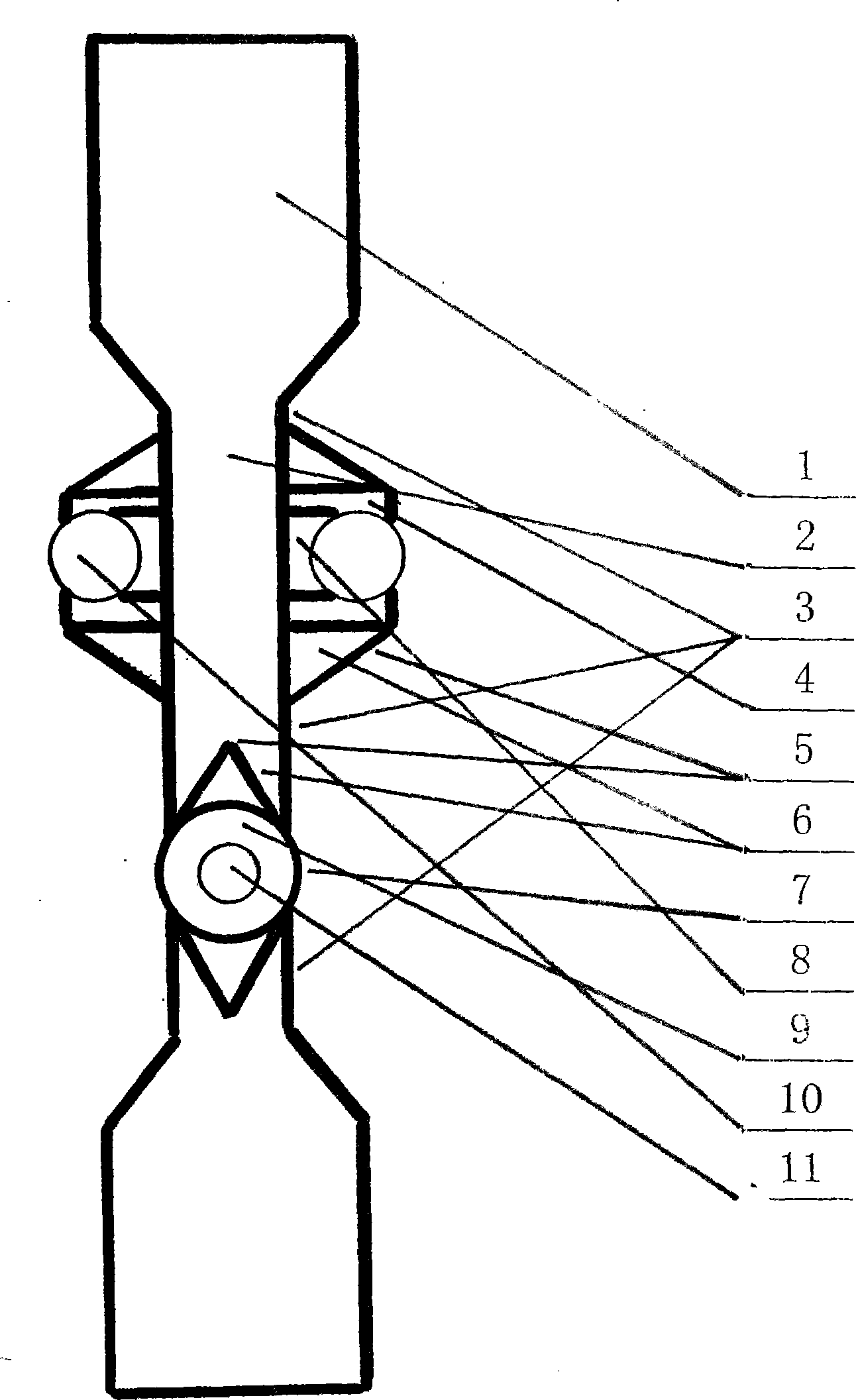
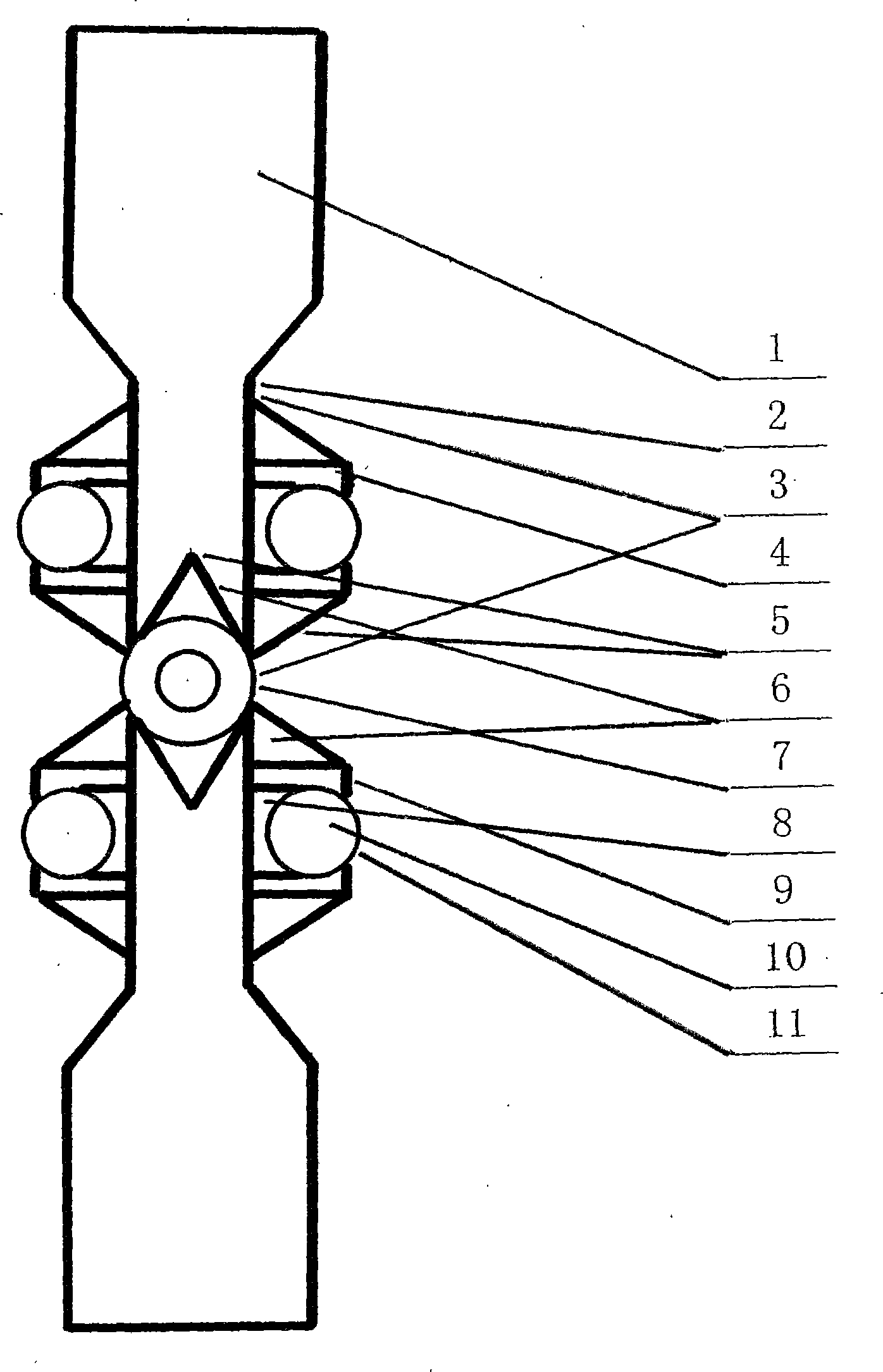
[0010] like figure 1 As shown: the coupling sucker rod body (2) is integrally and combinedly connected with a sucker rod standard body (4), and the sucker rod standard body (4) is combined with a magnet anti-wax body (8) and a rolling friction ball (10 ), the sucker rod standard body (4) has a water-facing line (5), a water-facing surface (6), a rolling friction hole (7), a sliding friction surface (9), and a rolling friction ball (10) is exposed from the rolling friction hole (7) The surface of the sucker rod is the rolling friction surface (11), and the space between the sucker rod standard bodies (4) is the well fluid flow channel (3).

[0011] like figure 2 Shown: the sucker rod standard body (4) has the overall structure schematic diagram of 5 sucker rod standard bodies (4).

[0012] The optimum number of sucker rod standard bodies (4) on the co...


PUM


Abstract

The invention relates to a centering anti-eccentric anti-waxing sucker-rod coupling and belongs to the field of petroleum and gas development. According to a sliding and rolling combined friction way, a magnet anti-waxing body (8) is arranged below friction balls (10); a sucker-rod standard body (4) is designed according to a fluid mechanics principle and is combined with the sucker-rod coupling; with a water facing line (5), a water facing surface (6) and an overflow surface (7), the overflow area of a well liquid flow passage (3) is guaranteed and the liquid flow resistance is reduced, so that the sucker-rod standard body (4) becomes a standard part of the sucker-rod coupling; the resistance to well liquid by the sucker-rod standard body (4) is minimized; the rolling of the friction balls (10) plays a main role while sling friction surfaces (9) play a secondary role; the magnet is free of influence of wax, and the sucker-rod standard body (4) is designed according to the shape of a submarine, so that the resistance to the well liquid is reduced.

Description

technical field [0001] The invention relates to a straightening anti-eccentric wear anti-wax deposition sucker rod coupling belonging to the field of petroleum and natural gas development. Background technique [0002] There are many reasons for the eccentric wear of the sucker rod and the tubing. In order to solve this problem, a centralizer has been developed, but the space between the sucker rod and the tubing is limited. This limited space is where the well fluid rises from the bottom of the well to the surface. The centralizer is working in this space. The centralizer occupies this limited space, which reduces the flow area and reduces the oil well production. At the same time, the centralizer works in the flowing well fluid and produces Resistance, this resistance increases the load of the sucker rod, causing damage to the sucker rod, and at the same time increases the power consumption and increases the mining cost. The current centralizer does not solve this problem....

Claims


Application Information

Patent Timeline
IPC IPC(8): E21B17/02E21B17/10
CPCE21B17/1085E21B17/04E21B17/1071E21B37/00
Inventor 王福成
Owner 王福成
Learn More