Oil return rail

An oil rail and oil-passing technology, which is applied in the direction of condensed fuel collection/return, etc., can solve the problems of inconvenient operation of the oil return pipe, increase the special parts of the whole machine, affect the installation efficiency, etc., to improve the assembly quality and the reliability and protection of the fuel system. Fuel system, the effect of reducing production takt time

Active Publication Date: 2015-01-28
GUANGXI YUCHAI MASCH CO LTD
View PDF6 Cites 2 Cited by
  • Summary
  • Abstract
  • Description
  • Claims
  • Application Information

AI Technical Summary

Problems solved by technology

[0008] Disadvantage 1: Most of the oil pipes of Duotong are integral design, the shape of the oil pipe is complicated, the production is difficult, and it is easy to deform during transportation, easy to assemble, and the stress is large.
[0009] Disadvantage 2: If multiple oil pipes are supplied separately, there will be a situation where multiple joints are connected to each other. The multi-way oil pipe joints have no fixed installation plane due to the small pipe joints, and there is a great risk of oil leakage
[0011] Disadvantage 1: The existing fuel distributors are all processed from a steel block or made of castings. The steel blocks used are not of standard specifications. They need to be cut many times before processing the oil inlet and outlet and oil passages, and the castings need to be molded.
[0012] Disadvantage 2: The fuel distributor is mostly a special part developed for a certain model, which has poor versatility, increases the special parts of the whole machine, and prolongs the development cycle and cost of the whole machine
[0013] Disadvantage 3: The fuel distributors are all blocky, all the oil pipes are piled up, and the whole machine is not beautiful
[0014] Disadvantage 4: When there are many other parts around the fuel distributor, it is inconvenient to install several oil return pipes together, which affects the installation efficiency

Method used


Image

  • Oil return rail
  • Oil return rail

Examples


Embodiment Construction

[0026] The specific embodiments of the present invention will be described in detail below in conjunction with the accompanying drawings, but it should be understood that the protection scope of the present invention is not limited by the specific embodiments.

[0027] Unless expressly stated otherwise, throughout the specification and claims, the term "comprise" or variations thereof such as "includes" or "includes" and the like will be understood to include the stated elements or constituents, and not Other elements or other components are not excluded.

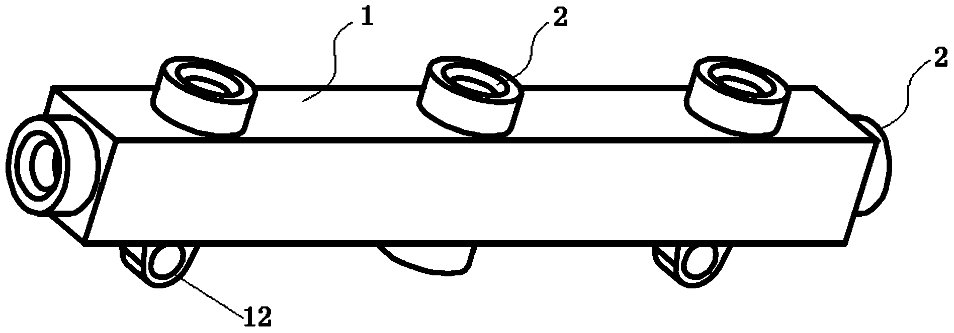
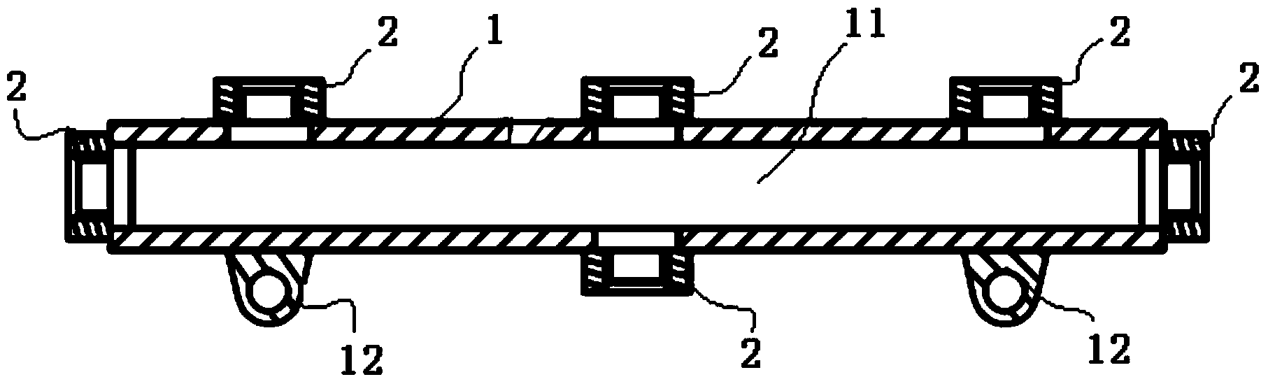
[0028] Such as figure 1 with figure 2 As shown, the specific structure of the oil return rail according to the specific embodiment of the present invention includes: an oil return rail main body 1 and a plurality of oil pipe joints 2 fixed on the oil return rail main body, wherein the oil return rail main body 1 has an oil return rail The main oil passage, the fuel return pipes of the fuel injection pump, fuel injector a...


PUM


Abstract

The invention discloses an oil return rail. The oil return rail comprises an oil return rail main body which is in a tubular shape and an oil pipe connector; the oil return main body is provided with a pipe chamber which is served as an oil return rail main body oil channel; the lateral wall and two ends of the oil return rail main body are provided with oil passing openings which are communicated with the pipe chamber; an installation boss is arranged on the lower lateral wall of the oil return rail main body; the oil pipe connector is provided with an axial internal threaded hole which is in threaded connection with a pipe nut of a fuel oil return pipe in a matching mode; the oil pipe connector is correspondingly fixed on the lateral wall of the oil return rail main body and the oil passing openings at two ends by welding. The oil return rail has the advantages of being convenient to install, reducing production takt, improving the assembling quality and the fuel oil system reliability, enabling an integral machine to be attractive in arrangement and being easy to popularize and use; being strong in universality, shortening the product development period and reducing research and development costs; being stable in oil return pressure and well protecting a fuel system; reducing the number of special purpose parts and accordingly reducing manufacturing costs, purchasing costs and inventory management costs.

Description

technical field [0001] The invention relates to the field of engines, in particular to an oil return rail. Background technique [0002] In addition to fuel supply, some parts such as fuel injection pump, fuel injector and common rail pipe of internal combustion engine fuel system also need to return fuel to better realize their functions. Therefore, multiple fuel return pipes should be designed to return fuel to the fuel tank at the same time. [0003] In order to avoid connecting multiple oil pipes to the fuel tank, and to concentrate the fuel into one oil pipe to flow back to the fuel tank, there are two existing methods: [0004] 1. The oil pipe of the multi-way joint, the oil return pipe of each part that needs to return oil is connected together through the multi-way joint. [0005] 2. Add a fuel distributor, the fuel return pipes are all connected to the fuel distributor, and the fuel distributor is then connected to a fuel tank. [0006] The prior art has the follo...

Claims


Application Information

Patent Timeline
Patent Type & Authority Applications(China)
IPC IPC(8): F02M33/08
Inventor 王雪光陶喜军
Owner GUANGXI YUCHAI MASCH CO LTD
Why Eureka
Try Eureka