Crowded ball bearing

A technology of full ball bearings and bearing outer rings, applied in the field of bearings, can solve problems such as small bearing capacity, separation of bearing inner rings and bearing outer rings, wear of balls and cages, etc., to increase bearing capacity, reduce wear, The effect of increasing the service life

Inactive Publication Date: 2015-01-28
NINGBO GREAT GRP
View PDF5 Cites 5 Cited by
  • Summary
  • Abstract
  • Description
  • Claims
  • Application Information

AI Technical Summary

Problems solved by technology

[0002] Existing bearings generally include a bearing inner ring, a bearing outer ring, balls and a cage. When the bearing is processed, the bearing inner ring and the outer ring are arranged tangentially, and then balls are placed between the bearing inner ring and the bearing outer ring. Then move the center of the inner ring of the bearing to coincide with the center of the outer ring of the bearing. During this process, the balls are loaded between the inner ring of the bearing and the outer ring of the bearing. Due to this processing method, the balls cannot fill the entire outer ring of the bearing and the inner ring of the bearing. The gap between the rings, if the balls move to one side at the same time, it may cause the inner ring of the bearing and the outer ring of the bearing to separate and cause danger. Therefore, after the balls are dispersed, the balls are kept in a dispersed state by the cage.
The bearings processed only in this way have the following disadvantages: 1. The space between the inner ring and the outer ring of the bearing is not filled with balls, so the bearing capacity of the bearing is small; 2. Since the balls and the cage are in surface contact, Therefore, the friction surface between the cage and the ball is relatively large, and the wear between the ball and the cage is serious, so that the overall life of the bearing is short
However, since the balls can pass through after the first notch and the second notch are aligned, there is a certain risk when receiving lateral stress during use. In order to prevent the balls from running out, both sides of the balls of this full-ball bearing still need Set the cage, which brings the disadvantages of the cage, that is, the wear between the ball and the cage is serious, so that the overall life of the bearing is short

Method used


Image

  • Crowded ball bearing
  • Crowded ball bearing

Examples


Embodiment Construction

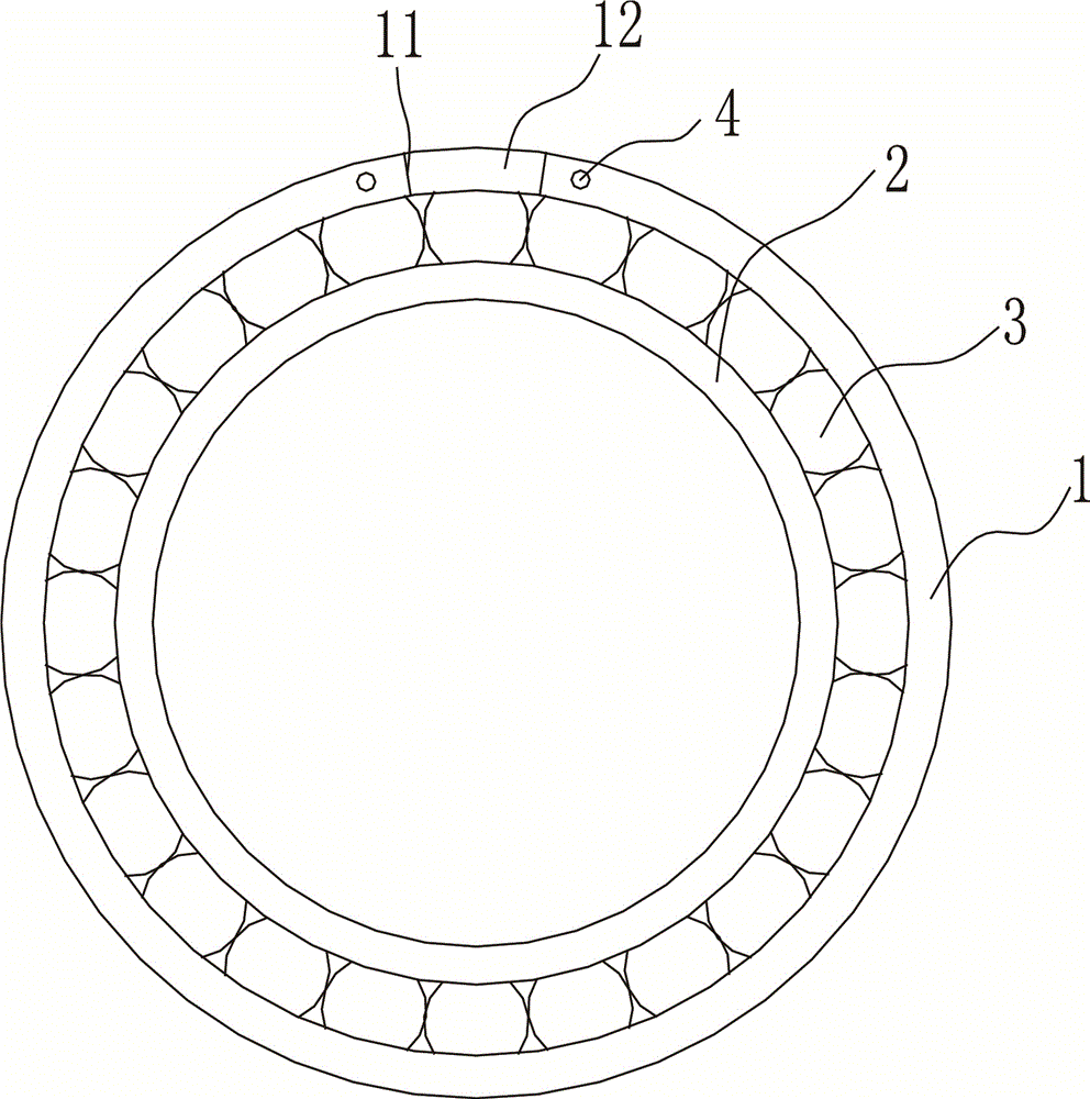
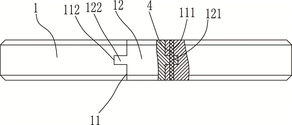
[0010] The present invention will be described in further detail below in conjunction with accompanying drawing and specific embodiment: see Figure 1 to Figure 2 , a full ball bearing, comprising a bearing outer ring 1 and a bearing inner ring 2, a ball 3 is arranged between the bearing outer ring 1 and the bearing inner ring 2, and a fracture 11 is arranged on the bearing outer ring 1, The fracture 11 is provided with an engaging block 12, the ball 3 can pass through the fracture 11, the engaging block 12 is provided with at least two first through holes 121, and the two sides of the fracture 11 are provided with There are at least two second through holes 111. When the engaging block 12 is installed in the fracture 11, the first through hole 121 is coaxial with the second through hole 111, and the first through hole 121 A pin 4 is arranged in the second through hole 111 . When this kind of bearing 4 is installed, balls 3 are loaded into the fracture 11 so that the gap betw...


PUM


Abstract

The invention discloses a crowded ball bearing which comprises an outer bearing ring and an inner bearing ring, wherein balls are arranged between the outer bearing ring and the inner bearing ring; an incision is formed in the outer bearing ring; a clamping block is arranged at the incision; the balls can pass through the incision; at least two first through holes are formed in the clamping block; at least two second through holes are formed in two sides of the incision; when the clamping block is arranged in the incision, the first through holes and the second through holes are coaxial; insertion pins are arranged in the first through holes and the second through holes. By virtue of the structure, the bearing capacity of the bearing is improved, and retainers for preventing the balls from falling off are not needed, so that surface contact between the balls and the retainers is avoided, abrasion to the balls is reduced, and the service life is prolonged.

Description

technical field [0001] The invention belongs to the technical field of bearings, in particular to a full ball bearing. Background technique [0002] Existing bearings generally include a bearing inner ring, a bearing outer ring, balls and a cage. During bearing processing, the bearing inner ring and the outer ring are set tangentially, and then balls are placed between the bearing inner ring and the bearing outer ring. Then move the center of the inner ring of the bearing to coincide with the center of the outer ring of the bearing. During this process, the balls are loaded between the inner ring of the bearing and the outer ring of the bearing. Due to this processing method, the balls cannot fill the entire outer ring of the bearing and the inner ring of the bearing. The gap between the rings, if the balls move to one side at the same time, it may cause the inner ring of the bearing and the outer ring of the bearing to separate and cause danger. Therefore, after the balls ...

Claims


Application Information

Patent Timeline
Patent Type & Authority Applications(China)
IPC IPC(8): F16C33/58F16C19/16
Inventor 戎伟军李鹏
Owner NINGBO GREAT GRP
Why Eureka
Try Eureka