Double-segment seal gate valve

A gate valve and valve body technology, which is applied in the field of double-seal gate valves, can solve the problems of safety protection of discharge pressure, scratched gate and valve seat, and inability to discharge under pressure, and achieves improved wear resistance, reliable bilateral sealing and adhesion. low force effect

Active Publication Date: 2015-01-28
自贡新比隆阀门有限公司
View PDF6 Cites 3 Cited by
  • Summary
  • Abstract
  • Description
  • Claims
  • Application Information

AI Technical Summary

Problems solved by technology

[0004] Existing gate valves generally use double gate valve seat rigid seal or single gate valve seat elastic seal to seal with the upper and lower valve seats at the same time. Stones, wood blocks, cement, iron filings, debris, etc. are deposited in the groove of the valve body cavity. In this case, the gate cannot be closed in place, and the seal cannot be formed. The valve cannot function as a switch, and sometimes even scratches the gate. The sealing surface with the valve seat may even get stuck, causing leakage, and it is quite difficult to repair the sealing surface
[0005] The traditional gate valve is in a closed state, and sometimes the medium in the gate groove will increase abnormally, and some media will increase abnormally when the temperature rises, so the gate is in a sealed state of the groove, and the pressure cannot be discharged. Can withstand the pressure range, it will produce a burst or explosion
[0006] Existing gate valves can only achieve a single function of sealing, and cannot discharge pressure to achieve safety protection under abnormal boosting conditions. If the existing gate valves are used under abnormal boosting conditions, there will be safety hazards

Method used


Image

  • Double-segment seal gate valve
  • Double-segment seal gate valve
  • Double-segment seal gate valve

Examples


Embodiment 1

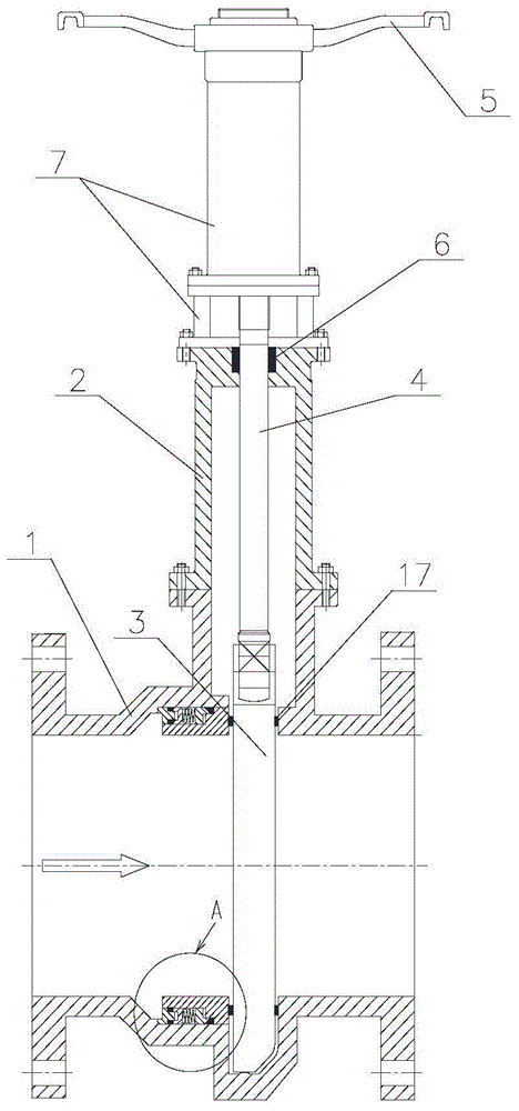
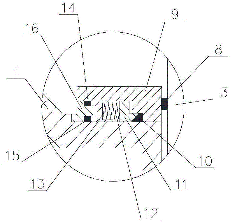
[0071] A double-stage sealed gate valve. The gate valve includes a valve body, a valve cover, a gate plate and a switch body. The valve body is cylindrical. The valve body includes an upstream valve body, a valve body cavity, a gate valve groove and a downstream valve body. The upstream valve body and A gate plate and a sealing device perpendicular to the axial direction of the valve body are arranged between the downstream valve bodies; the sealing device includes a cylindrical valve seat support with the same inner diameter and the outer diameter increases from upstream to downstream in the groove of the inner wall of the middle cavity of the valve body. Ring and the front cover, packing ring, spring support seat, spring and back cover which are successively arranged in the gap between the valve seat support ring and the cavity groove of the valve body along the direction from upstream to downstream; The axial direction of the valve body is vertical.

[0072] The valve cover...

Embodiment 2

[0107] A double-stage sealed gate valve. The gate valve includes a valve body, a valve cover, a gate plate and a switch body. The valve body is cylindrical. The valve body includes an upstream valve body, a valve body cavity, a gate valve groove and a downstream valve body. The upstream valve body and A gate plate and a sealing device perpendicular to the axial direction of the valve body are arranged between the downstream valve bodies; the sealing device includes a cylindrical valve seat support with the same inner diameter and the outer diameter increases from upstream to downstream in the groove of the inner wall of the middle cavity of the valve body. Ring and the front cover, packing ring, spring support seat, spring and back cover which are successively arranged in the gap between the valve seat support ring and the cavity groove of the valve body along the direction from upstream to downstream; The axial direction of the valve body is vertical.

[0108] The valve cover...

Embodiment 3

[0143] A double-stage sealed gate valve. The gate valve includes a valve body, a valve cover, a gate plate and a switch body. The valve body is cylindrical. The valve body includes an upstream valve body, a valve body cavity, a gate valve groove and a downstream valve body. The upstream valve body and A gate plate and a sealing device perpendicular to the axial direction of the valve body are arranged between the downstream valve bodies; the sealing device includes a cylindrical valve seat support with the same inner diameter and the outer diameter increases from upstream to downstream in the groove of the inner wall of the middle cavity of the valve body. Ring and the front cover, packing ring, spring support seat, spring and back cover which are successively arranged in the gap between the valve seat support ring and the cavity groove of the valve body along the direction from upstream to downstream; The axial direction of the valve body is vertical.

[0144] The valve cover...


PUM


Abstract

The invention provides a double-segment seal gate valve which comprises a valve body, a valve deck, a flashboard and a switch body, wherein the valve body is cylindrical and comprises an upstream valve body, a valve body middle cavity, a gate valve slot and a downstream valve body; the gate valve slot is formed between the valve body middle cavity and the downstream valve body, and the flashboard axially perpendicular to the valve body and a sealing device are arranged between the upstream valve body and the downstream valve body; the sealing device comprises cylindrical valve seat supporting rings, a front cover, a packing ring, a spring supporting seat, a spring and a rear cover; the valve seat supporting rings are arranged in an inner wall groove of the valve body middle cavity, the internal diameters of the valve seat supporting rings are equal, and the external diameters of the valve seat supporting rings are progressively increased in an upstream direction to a downstream direction; the front cover, the packing ring, the spring supporting seat, the spring and the rear cover are sequentially arranged in gaps between the valve seat supporting rings and the groove of the valve body middle cavity; the switch body is arranged at one end of the flashboard and axially perpendicular to the valve body. Under the condition that the pressure of the gate valve slot abnormally rises, the gate valve can quickly discharge pressure from an upstream pipeline to realize safety protection.

Description

technical field [0001] The invention relates to a valve, in particular to a double-stage sealing gate valve. Background technique [0002] The gate valves used in regulating and closing devices are widely used in pipelines such as tap water, sewage, construction, petroleum, chemical industry, food, medicine, textile, electric power, shipbuilding, metallurgy, and energy systems. [0003] The opening and closing part of the gate valve is the gate, and the movement directions of the gate and the fluid are perpendicular to each other, while the gate valve can only be fully opened and fully closed. When the gate valve is closed, the sealing surface can be sealed only by the medium pressure, that is, only by the medium. The pressure presses the sealing surface of the gate to the valve seat on the other side to ensure the sealing of the sealing surface, which is self-sealing. In order to ensure the sealing surface sealing, most of the gate valve adopts forced sealing, that is to s...

Claims


Application Information

Patent Timeline
IPC IPC(8): F16K3/02F16K3/30F16K27/04F16K31/60
CPCF16K3/0227F16K3/16F16K3/30F16K3/312F16K25/04F16K27/044
Inventor 洪元生
Owner 自贡新比隆阀门有限公司
Why Eureka
Try Eureka