Support plate capable of improving performance of electric wetting displayer, manufacture technology thereof and electric wetting displayer

An electrowetting display and manufacturing process technology, applied in the direction of instruments, optical components, optics, etc., can solve problems such as insufficient surface area, oil ingress, and affecting device reliability, so as to improve device quality, avoid short circuits, and ensure integrity Effect

Active Publication Date: 2015-01-28
SOUTH CHINA NORMAL UNIVERSITY +2
View PDF5 Cites 3 Cited by
  • Summary
  • Abstract
  • Description
  • Claims
  • Application Information

AI Technical Summary

Problems solved by technology

However, there is a problem with this method, that is, when the hydrophobic layer material is etched into a pattern of a pixel grid shape, there will be gaps due to the bonding between the hydrophobic layer and the pixel wall, which will cause vibrations above the hydrophobic layer after multiple switches. Water (or ionic liquids and saline solutions such as sodium chloride aqueous solution) short circuit after contact with the bottom electrode, thus affecting the reliability of the device
[0006] Moreover, the above schemes all have the risk of oil crossing the pixel wall and entering another pixel grid
As in the solution in WO 2003 / 071346, the insulating layer is easily deformed by heating, causing it to cover (climb up) the side of the pixel wall, resulting in insufficient surface area of ​​the hydrophilic material pixel wall between pixels, thus causing Oil jumps over the cell wall into another pixel
However, in the above-mentioned scheme of making the pixel wall directly on the support plate, the side of the pixel wall is completely surrounded by the material of the hydrophobic layer, and there is a risk that the oil cannot be effectively prevented from jumping over and jumping into another pixel grid.

Method used


Image

  • Support plate capable of improving performance of electric wetting displayer, manufacture technology thereof and electric wetting displayer
  • Support plate capable of improving performance of electric wetting displayer, manufacture technology thereof and electric wetting displayer
  • Support plate capable of improving performance of electric wetting displayer, manufacture technology thereof and electric wetting displayer

Examples


Embodiment Construction

[0025] It should be noted that, in the case of no conflict, the embodiments in the present application and the features in the embodiments can be combined with each other.

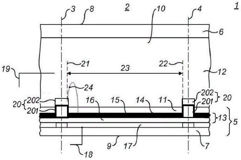
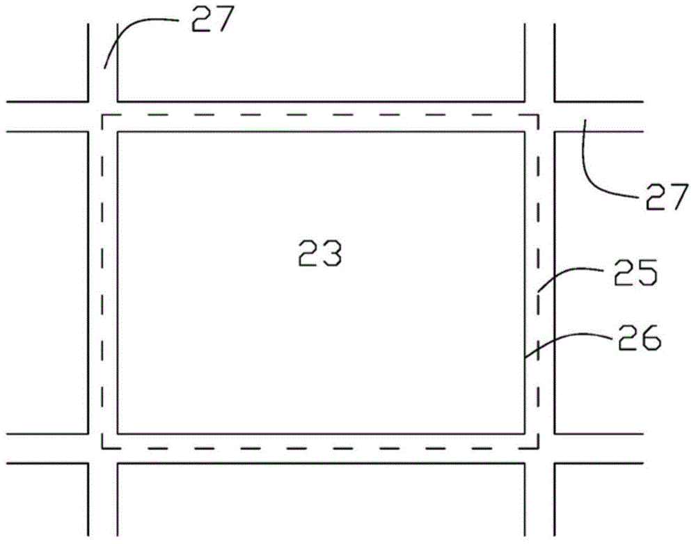
[0026] Such as Figure 1~Figure 2 as shown, figure 1 A partial cross-section of an electrowetting display is shown. The electrowetting display comprises a plurality of picture elements 2, one of which is shown in the figure. The lateral extent of the cell 2 is indicated by two dashed lines 3 and 4 in the figure. The pixel 2 includes a first support plate 5 and a second support plate 6 . These support plates 5 and 6 may be separate parts of each picture element 2 , but preferably these support plates 5 and 6 are shared by a plurality of picture elements 2 . The support plates 5 and 6 may comprise glass or polymer substrates 7 and 6 and may be rigid or flexible. The pixel wall 20 is arranged on the first support plate 5, more specifically, on the dielectric layer 16 or the first electrode 17, not on the...


PUM


Abstract

The invention provides a manufacture technology of a support plate capable of improving performance of an electric wetting displayer. The manufacture technology of the support plate capable of improving the performance of the electric wetting displayer includes following steps: manufacturing a first layer picture element wall on the support plate; then, arranging a hydrophobic layer, and further arranging a protection layer on the hydrophobic layer so as to perform surface modification on the hydrophobic layer and change the hydrophobic layer on the upper surface of the first layer picture element wall into a hydrophilic layer; finally, arranging a second layer picture element wall on the hydrophilic layer. The manufacture technology of the support plate capable of improving the performance of the electric wetting displayer prevents damage to the hydrophobic layer, guarantees completeness of the hydrophobic layer, can effectively prevent liquid above the hydrophobic layer from entering the edge of the hydrophobic layer and apertures in picture element material, and prevents the problem that an upper support plate and a lower support plate are short circuited, and simultaneously can effectively prevent oils from penetrating through the picture element walls, and improves device quality. The invention further provides the support plate prepared by using the manufacture technology and the electric wetting displayer with the support plate. The support plate capable of improving the performance of the electric wetting displayer, the manufacture technology thereof and the electric wetting displayer can be used in electric wetting display.

Description

technical field [0001] The invention relates to the technical field of electrowetting display, in particular to a support plate for improving the performance of an electrowetting display, a manufacturing process thereof, and an electrowetting display including the support plate. Background technique [0002] Electrowetting is a microfluidic phenomenon that has begun to be widely used as an actuation mechanism for various fluidic and electro-optical devices. At present, electrowetting display technology has been widely used. It provides a display unit based on electrowetting technology, including a fluid chamber and an electrode structure, wherein the fluid chamber contains a conductive fluid and a non-conductive fluid, and the fluids are in contact with each other. Immiscible, wherein the electrode structure comprises a first electrode in contact with the conductive fluid and a second electrode arrangement disposed at the chamber wall. [0003] International patent applicat...

Claims


Application Information

Patent Timeline
Patent Type & Authority Applications(China)
IPC IPC(8): G02B26/00
Inventor 吴昊李发宏罗伯特·安德鲁·海耶斯周国富
Owner SOUTH CHINA NORMAL UNIVERSITY
Why Eureka
Try Eureka