Method for carrying out cutter back-off compensation on multi-shaft processing path of weak-rigidity cutter

A multi-axis processing and processing path technology, applied in the direction of instruments, computer control, simulators, etc., to achieve the effects of suppressing the size of parts out of tolerance, ensuring one-time molding, and ensuring processing efficiency and processing accuracy

Active Publication Date: 2015-01-28
JIANGSU JITRI HUST INTELLIGENT EQUIP TECH CO LTD
View PDF11 Cites 10 Cited by
  • Summary
  • Abstract
  • Description
  • Claims
  • Application Information

AI Technical Summary

Problems solved by technology

[0004] The purpose of the present invention is to solve the problems mentioned in the above background technology section by a method of tool compensation for the multi-axis machining path of weakly rigid tools

Method used


Image

  • Method for carrying out cutter back-off compensation on multi-shaft processing path of weak-rigidity cutter
  • Method for carrying out cutter back-off compensation on multi-shaft processing path of weak-rigidity cutter
  • Method for carrying out cutter back-off compensation on multi-shaft processing path of weak-rigidity cutter

Examples


Embodiment Construction

[0030] The present invention will be further described below in conjunction with drawings and embodiments. It should be understood that the specific embodiments described here are only used to explain the present invention, but not to limit the present invention. In addition, it should be noted that, for the convenience of description, only parts related to the present invention are shown in the drawings but not all content.

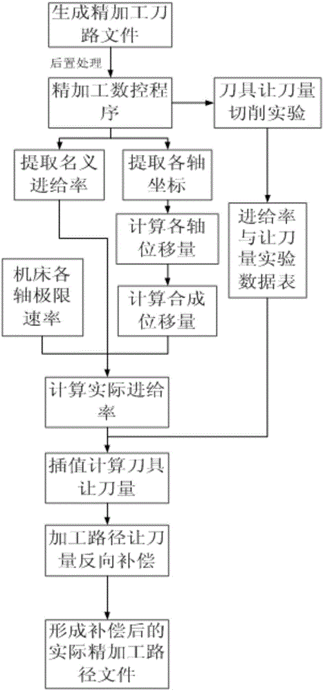
[0031] Please refer to figure 1 as shown, figure 1 It is a flow chart of a method for tool clearance compensation for a multi-axis machining path of a weakly rigid tool provided by an embodiment of the present invention.

[0032] In this embodiment, the method for performing tool yield compensation on the multi-axis machining path of a weakly rigid tool specifically includes the following steps:

[0033] S101. Generate a finishing tool path file according to the geometric shape and process parameters of the part, and perform post-processing to convert...


PUM


Abstract

The invention discloses a method for carrying out cutter back-off compensation on a multi-shaft processing path of a weak-rigidity cutter. According to the method, a relation between all cutter spacing multi-shaft processing actual speeds and cutter back-off amounts is taken into consideration to generate an overcut path in a reverse mode; and a weak-rigidity tool is used for carrying out cutter back-off deformation processing. The part dimension difference exceeding is effectively reduced or inhibited; the one-time moulding is ensured; multi-times repeated cutting is not required; and the processing efficiency and processing precision are guaranteed.

Description

technical field [0001] The invention relates to the technical field of numerical control machining, in particular to a method for tool give-up compensation for a multi-axis machining path of a weakly rigid tool. Background technique [0002] As a high-precision and efficient cutting processing method, multi-axis CNC milling is widely used in aerospace, shipbuilding, automobiles, molds and other fields, especially in the processing of parts with complex curved surfaces, such as blisks. With the continuous increase in the demand for blisks in the aerospace industry, various types of blisks are emerging in an endless stream. The overall blisk has a large number of blades, narrow flow channels, and long blade overhangs. Therefore, the tools used for processing must be thin and long, with a large aspect ratio and weak tool rigidity. When finishing the blade, the weakly rigid tool is prone to severe tool give-up, which causes the actual size of the profile to exceed the theoretic...

Claims


Application Information

Patent Timeline
IPC IPC(8): G05B19/404
CPCG05B19/404
Inventor 代星唐祥武严思杰鄢龙志丁汉
Owner JIANGSU JITRI HUST INTELLIGENT EQUIP TECH CO LTD
Why Eureka
Try Eureka