3D image stitching method and apparatus

An image stitching and 3D technology, applied in the field of image stitching, can solve the problems of difficult reuse of models, inability to meet the actual needs of users for 3D scene presentation, and large workload of 3D reverse modeling, and achieve the effect of overcoming the large workload.

Inactive Publication Date: 2015-01-28
华雁智能科技(集团)股份有限公司
View PDF4 Cites 17 Cited by
  • Summary
  • Abstract
  • Description
  • Claims
  • Application Information

AI Technical Summary

Problems solved by technology

[0004] Although the above methods can realize the visualization of 3D scenes, because of the different monitoring sites or equipment, for example, each substation has different types of equipment and unique spatial distribution characteristics, if the above-mentioned 3D reverse modeling method is used for 3D scene It is necessary to model each device and location, which leads to heavy workload, long cycle and difficult model reuse of 3D reverse modeling, which cannot meet the actual needs of users for 3D scene display.

Method used


Image

  • 3D image stitching method and apparatus
  • 3D image stitching method and apparatus
  • 3D image stitching method and apparatus

Examples


Embodiment approach

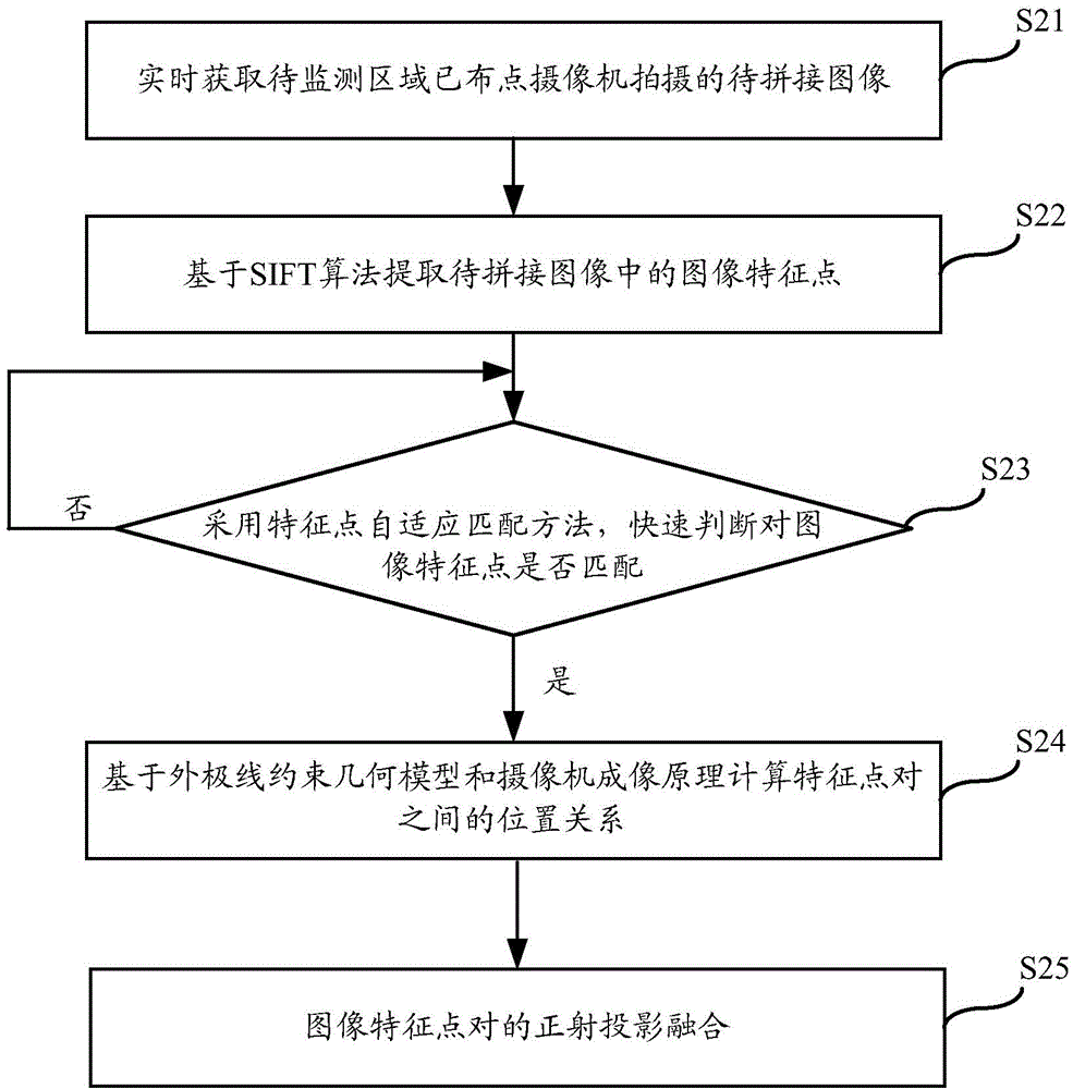
[0031] Such as figure 2 As shown, the present invention also provides a kind of preferred implementation method based on above-mentioned idea, and this method mainly comprises:

[0032] Step S21: Obtain in real time the images to be spliced ​​taken by the cameras deployed in the area to be monitored.

[0033] In the monitoring area, cameras have been deployed. The monitoring images of the monitoring area can be obtained in real time through the deployed cameras.

[0034] For the images to be spliced ​​acquired by the deployed cameras, there is an overlapping area with a set ratio between them. Preferably, there is at least a 20% overlapping area between any two images to be spliced.

[0035] In addition, in this method, the camera information of the deployed cameras is pre-acquired, and the specific camera information may include the number of cameras, the type of cameras, and the physical parameters of the cameras. For the camera type, the range of options includes ball c...


PUM


Abstract

The invention relates to the technical field of image stitching, in particular to a 3D image stitching method and apparatus. The method includes the steps of obtaining images which are to be stitched and shot by a distributed camera in a target monitoring area, wherein an overlapping area in a set ratio is arranged between every two stitched images; determining the position correspondence of image feature points of the images to be stitched; determining a geometric projection plane through overall orientation information of the image feature points; projecting all of the images to be stitched to the geometric projection plane according to the position correspondence of the image feature points to determine an overall diagram framework; stitching the images according to overall coordinates of the image feature points to obtain a three-dimensional panoramic image. The3D image stitching method and apparatus can quickly perform stitching for images in the target monitoring area to achieve 3D scene display and effectively overcomes the deficiencies of heavy workload, long cycle and model re-use difficulty of existing reverse three-dimensional modeling so as to perfectly meet the actual needs of three-dimensional scene display of users.

Description

technical field [0001] The present invention relates to the technical field of image mosaic, in particular to a 3D image mosaic method and device. Background technique [0002] At present, camera equipment is mostly used to monitor key places and key equipment. The images obtained by monitoring with camera equipment are all two-dimensional images, and each monitoring equipment can only obtain part of the images of the monitoring site or equipment, which is not convenient for users to conduct panoramic monitoring of the monitoring site or equipment. For example, in the monitoring of substations, dozens of cameras are arranged to monitor different physical and scene objects respectively. How to display and monitor substation scenes based on 3D panoramic visualization is one of the business needs of power users. [0003] The existing 3D panoramic visualization scene display and monitoring methods are mainly 3D patrolling, simulation training and equipment asset management, etc...

Claims


Application Information

Patent Timeline
Patent Type & Authority Applications(China)
IPC IPC(8): G06T15/00
CPCG06T3/4038G06T15/00G06T17/00
Inventor 胡娟颜江冯宇
Owner 华雁智能科技(集团)股份有限公司
Why Eureka
Try Eureka