
Rapid measurement and analysis method for rock mass structural features of underground engineering

A technology of structural characteristics, measurement and analysis, which is applied in the fields of mining engineering, shaft engineering, geological engineering, and geotechnical engineering. Analyze, ensure accuracy and timeliness, and overcome the effect of heavy on-site workload

Inactive Publication Date: 2019-02-22
NORTHEASTERN UNIV
View PDF4 Cites 6 Cited by
  • Summary
  • Abstract
  • Description
  • Claims
  • Application Information

AI Technical Summary

Problems solved by technology

However, the traditional surveying line method and sampling window method have no corresponding regulations on the selection of surveying line and sampling window. They are generally arranged along the axis of the roadway. The measurement method has problems such as heavy workload, lagging data statistics, long cycle, and large measurement error, which seriously affects the analysis and design of rock mass engineering stability by underground engineering designers, and increases the risk of unpredictable underground engineering.
At present, the development of measurement technology for rock mass structure characteristics in underground engineering mainly focuses on the research and development of non-contact measurement methods (laser scanning and stereo photography technology) to realize the digital acquisition of rock mass structure information, but there is no significant improvement in the measurement method , and there is no new fast and accurate measurement method proposed

Method used


Image

  • Rapid measurement and analysis method for rock mass structural features of underground engineering
  • Rapid measurement and analysis method for rock mass structural features of underground engineering
  • Rapid measurement and analysis method for rock mass structural features of underground engineering

Examples


Embodiment Construction

[0055] It should be noted that all directional indications (such as up, down, left, right, front, back...) in the embodiments of the present invention are only used to explain the relationship between the components in a certain posture (as shown in the accompanying drawings). Relative positional relationship, movement conditions, etc., if the specific posture changes, the directional indication will also change accordingly.

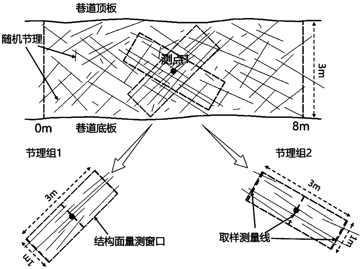
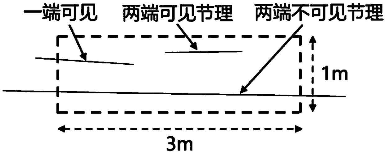
[0056] Such as Figure 1 to Figure 3As shown, the present invention provides a method for rapid measurement and analysis of structural characteristics of underground engineering rock mass, comprising the following steps:

[0057] Step 1. Determine the survey area: Determine the survey area according to the purpose of the survey. Identify the geometric distribution characteristics of large-scale geological structures such as faults in the survey area, and divide the survey area into several sub-areas with such large-scale rock mass structures as boundari...


PUM


Abstract

The invention relates to a rapid measurement and analysis method for rock mass structural features of underground engineering. The method comprises the following steps that: step one, a survey area isdetermined based on a survey purpose and the area is divided into a plurality of sub areas by using a large geological structure like a fault as a boundary; step two, a plurality of measuring pointsare divided in the survey area, wherein the measuring points are arranged in the survey area at intervals; step three, according to occurrence characteristics of the joints in the range of the measuring points, dominant joint groups are divided and joint measurement windows are arranged by using the center points of the measuring points as centers based on the trend occurrence characteristics of the dominant joint groups; and step four, the measurement and analysis of the tendency, the inclination angle, the average joint spacing and the average trace length of the joint are carried out basedon the joint measurement windows. Therefore, defects of large field work load, many needed measurement field indexes, and statistic analysis work delay due to the joint information full-sample measurement and statistics of the traditional surveying method are overcome; and the rapid and accurate measurement and analysis of rock mass structure surface of underground space are realized.

Description

technical field [0001] The invention relates to the technical fields of geological engineering, geotechnical engineering, mining engineering and shaft engineering, in particular to a rapid measurement and analysis method for underground engineering rock mass structure characteristics. Background technique [0002] Rock mass is the general term for in-situ media containing bedding, faults, joints, folds, and other structural features. The reason why rock mass is different from other engineering materials is that it contains various types of joints (rock mass structural planes) inside, which makes it have heterogeneous and anisotropic engineering properties. Obviously, the structure of rock mass has a decisive influence on the stability of rock mass in underground engineering. Therefore, in order to optimize the stability of underground engineering, it is necessary to measure and analyze the rock mass structure through certain means to find out the distribution law, developme...

Claims


Application Information

Patent Timeline
Patent Type & Authority Applications(China)
IPC IPC(8): G01D21/02G01C15/00G01C17/00
CPCG01C15/00G01C17/00G01D21/02
Inventor 金长宇吴超安龙李元辉徐帅于洪雯张建双刘建坡徐世达
Owner NORTHEASTERN UNIV
Learn More