
Split type stator structure

A stator structure, split technology, applied in the shape/style/structure of winding conductor, magnetic circuit shape/style/structure, shape/style/structure of winding insulation, etc., can solve the problem of low work efficiency, troublesome winding, etc. Obstructing motor performance and other problems, to achieve the effect of improving production efficiency, reducing defective rate and reducing cost

Inactive Publication Date: 2015-01-28
东莞福登机电有限公司
View PDF4 Cites 1 Cited by
  • Summary
  • Abstract
  • Description
  • Claims
  • Application Information

AI Technical Summary

Problems solved by technology

However, the stator structure of the existing capacitor-operated motor has the following problems: since the stator core and the insulating winding frame are integrally formed, and the winding can only be wound by passing through the slot, due to the limited width of the slot, Therefore, the operation space of the winding winding is limited, the winding is troublesome and the work efficiency is low; and because the notch needs to pass through the winding needle that works back and forth, a certain width must be reserved for the notch, so the design of the notch width is limited, and at the same time The winding needle is also easy to be damaged; and some types of motor stators require narrow slots to fully exert their performance, so the existing stator structure hinders the further improvement of the motor performance

Method used


Image

  • Split type stator structure
  • Split type stator structure
  • Split type stator structure

Examples


Embodiment Construction

[0024] In order to enable the examiner to further understand the structure, features and other purposes of the present invention, the attached preferred embodiments are attached with accompanying drawings in detail as follows. The embodiments illustrated in the accompanying drawings are only used to illustrate the technical solution of the present invention , not to limit the present invention.

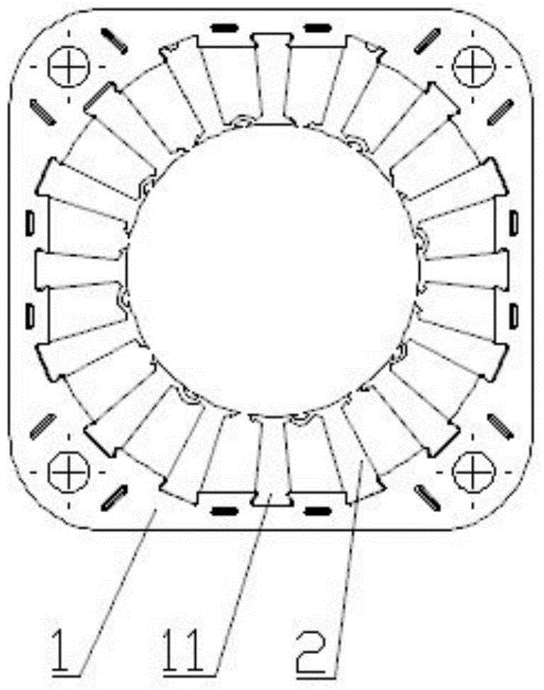
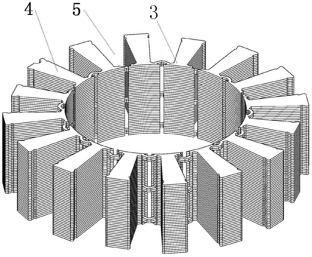
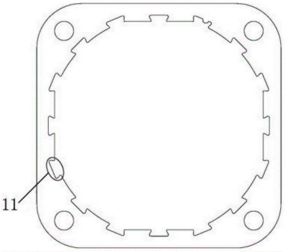
[0025] like Figure 1 to Figure 3 As shown, the present invention provides a split stator structure, including an outer ring stator 1 and an inner ring stator 2 sleeved inside the outer ring stator 1 . like figure 2 , image 3 As shown, the inner ring stator 2 is composed of an even number of original line slot yokes 3, and two adjacent original line slot yokes 3 are electrically connected by spaced pole jumps, and each original line slot yoke 3 Convex teeth 4 are evenly arranged in the circumferential direction, and wire slots 5 are formed between adjacent convex teeth 4. The ann...


PUM


Abstract

The invention discloses a split type stator structure. The split type stator structure comprises an outer circle stator and an inner circle stator; the outer circle stator sleeves the inner circle stator; the inner circle stator is formed by even number of original wire groove yokes; every two adjacent original wire groove yokes are electrically connected in a separate electrode breaking mode; protruding teeth are uniformly arranged on every original wire groove yoke along the circumferential direction of the inner circle stator; a wire groove position is formed between every two adjacent protruding teeth; an annular winding is connected onto every protruding tooth through the corresponding wire groove position in a sleeving mode; an insulating layer is arranged between the annular windings and the inner circle stator; every protruding tooth is provided with a plastic blocking piece which is used for fixing the corresponding annular winding. According to the split type stator structure, the inner circle stator is formed by the even number of original wire groove yokes, every two adjacent original wire groove yokes are electrically connected in a separate electrode breaking mode, and accordingly the assembly is convenient and the defective rate is reduced and the original stator is divided into the two portions in a new form and accordingly the production efficiency is greatly improved and the cost of the production and production equipment is reduced.

Description

technical field [0001] The invention relates to a motor accessory and a motor using the accessory, more specifically, to a split-type motor stator lamination structure. Background technique [0002] Most of the motor stator cores on the market are integral structures, and the stator windings are placed in the stator slots. When the windings are installed, it is necessary to manually insert the wires or use a special winding machine to wind them on the teeth. The manual insertion efficiency is low, and the special winding The machine equipment is expensive; at the same time, the winding end of the stator slot is long, and the amount of enameled wire is relatively large. In the prior art, there is an urgent need for a split-type stator core with convenient winding and less copper consumption. [0003] When producing the stator of the existing capacitor-operated motor, an integrally formed stator core is first produced, then an insulating bobbin is installed, and finally the w...

Claims


Application Information

Patent Timeline
IPC IPC(8): H02K1/14
CPCH02K1/145H02K3/18H02K3/34H02K3/48H02K2201/09
Inventor 许永福
Owner 东莞福登机电有限公司
Features
  • Generate Ideas
  • Intellectual Property
  • Life Sciences
  • Materials
  • Tech Scout
  • Unparalleled Data Quality
  • Higher Quality Content
  • 60% Fewer Hallucinations
Learn More