
Reception station device, transmission station device, communication system, reception method, transmission method and program

A communication method and technology of a communication system, applied in transmission systems, wireless communications, digital transmission systems, etc., can solve problems such as mutual interference of data signals and difficulty in decoding data signals at receiving stations

Inactive Publication Date: 2015-01-28
SHARP KK
View PDF4 Cites 53 Cited by
  • Summary
  • Abstract
  • Description
  • Claims
  • Application Information

AI Technical Summary

Problems solved by technology

In general, when the transmitting station transmits data signals for a plurality of receiving stations using the same wireless resource without performing prior separation processing on the transmitting station side, the data signals destined for the receiving stations using the same wireless resource are mutually incompatible with each other. interfere with each other and it becomes difficult for each receiving station to decode the data signal

Method used


Image

  • Reception station device, transmission station device, communication system, reception method, transmission method and program
  • Reception station device, transmission station device, communication system, reception method, transmission method and program
  • Reception station device, transmission station device, communication system, reception method, transmission method and program

Examples


no. 1 Embodiment approach

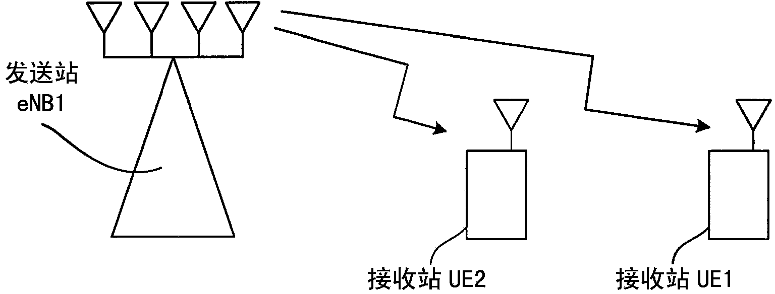
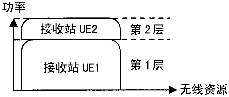
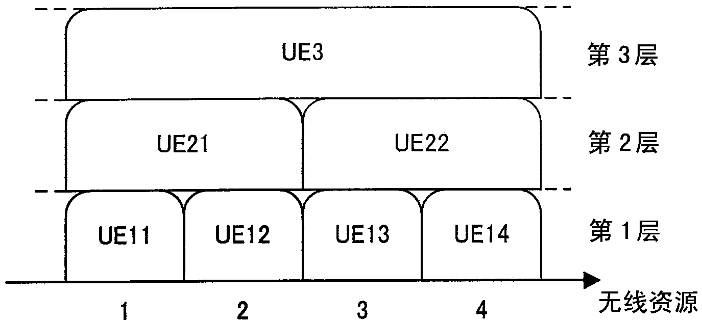
[0089] In this embodiment, a case where the communication line is a downlink (downlink) will be described. Although the following description assumes that the number of receiving stations communicating using the same radio resource is two, this embodiment is not limited thereto, and the number of receiving stations may be three or more. In addition, although transmission from one transmission station has been described, communication may be performed from two or more transmission stations using the same radio resource. In addition, in this case, a plurality of transmission stations transmit from different transmission positions. Therefore, if the space resources used by the transmission stations are different but the space resources used by the reception station are the same, the same wireless resource is used. Therefore, "using the same radio resource from two or more transmitting stations" means that the receiving station considers the same radio resource when receiving carr...

no. 2 Embodiment approach

[0251] The second embodiment will be described below. In the first embodiment, branch determination in replica signal generation processing is performed using error detection codes. However, if an error detection code is added, further parity bits will be added, the redundancy of the transmitted signal will increase, and even if the degree is not high, the data transmission efficiency will be degraded. In this embodiment, focusing on the fact that the error rate greatly affects the state of the propagation path and the modulation method, the power ratio of the multiplexed signal is used to perform branch determination in the replica signal generation process.

[0252] The configuration of the transmitting station device and the configuration of the receiving station device according to this embodiment are the same as those of the first embodiment. However, the processing of the decoding unit 209 of the receiving station apparatus is different from that of the first embodiment...

no. 3 Embodiment approach

[0274] In this embodiment, an example in which double encoding is performed by the encoding unit of the transmitting station apparatus will be described.

[0275] The configuration of the transmitting station device and the basic configuration of the receiving station device according to the present embodiment are similar to Image 6 , Figure 8 , Figure 9 as well as Figure 12 same. However, the processing of the encoding unit 101 of the sending station device and the processing of the decoding unit 209 and the re-encoding unit 241 in the replica generation unit of the receiving station device are different from those of the first embodiment, so the following describes the encoding unit 101, the re-encoding unit 241 and the decoding unit. The processing of 209 will be described.

[0276] Figure 33 It is a configuration diagram inside the encoding unit of the transmission station device in this embodiment.

[0277] The encoding unit 101 a is configured to include an er...


PUM


Abstract

In order to make it possible to efficiently generate a replica signal for a data signal addressed to another reception station and perform interference cancellation processing or interference reduction processing using the replica signal, a replica generation unit (232) returns an interference data signal inputted from a decoding unit (209) to a symbol string generated by a transmission station and not yet subjected to frequency demapping processing. The generated replica symbol string is outputted to an interference cancellation unit (231). The interference cancellation unit (231) subtracts a replica frequency domain signal inputted from the replica generation unit (232) from a frequency domain signal inputted from an FFT unit (204) to remove an undesired reception station signal. A symbol string obtained as the result of the subtraction is outputted to a signal separation unit (206). Two or more kinds of replica signal generation processing are provided, a selection from the two or more kinds of replica signal generation processing is performed according to the state of a propagation path and the contents of data signal reception processing, a replica signal is generated by the selected replica signal generation processing, and interference cancellation is performed.

Description

technical field [0001] The present invention relates to a receiving station device, a transmitting station device, a communication system, a receiving method, a transmitting method, and a program for communicating data signals for a plurality of receiving stations using the same radio resource. Background technique [0002] In recent cellular wireless communications, due to the rapid increase in data traffic, further improvement in transmission speed is expected. As a means of increasing the transmission speed, it is effective to perform communication using a large number of radio frequency bands and data transmission time, but the usable radio frequency band and data transmission time in cellular radio communication are limited. Therefore, in the next-generation wireless communication standards after further evolution of cellular wireless communication standards such as LTE (Long Term Evolution) or LTE-A (LTE-Advanced (advanced)), it is desired to use fewer wireless frequen...

Claims


Application Information

Patent Timeline
Patent Type & Authority Applications(China)
IPC IPC(8): H04J99/00H04B7/04H04J11/00
CPCH04J11/004H04B7/08H04J11/005H04B7/0452H04L1/0048H04L1/005H04W72/23H04W72/541H04J11/0023H04W72/0473
Inventor 草岛直纪
Owner SHARP KK
Learn More