Automatic pushing and clamping mechanism and method of arc-shaped grafting clamp
A grafting clip and arc-shaped technology are applied in the field of automatic push-clamp mechanism for arc-shaped grafting clips, which can solve the problem of low degree of automation and achieve the effects of reducing labor intensity, improving grafting success rate and simple structure.
- Summary
- Abstract
- Description
- Claims
- Application Information
AI Technical Summary
Problems solved by technology
Method used
Image

Examples
Embodiment Construction
[0035] Below in conjunction with embodiment, further illustrate the present invention.
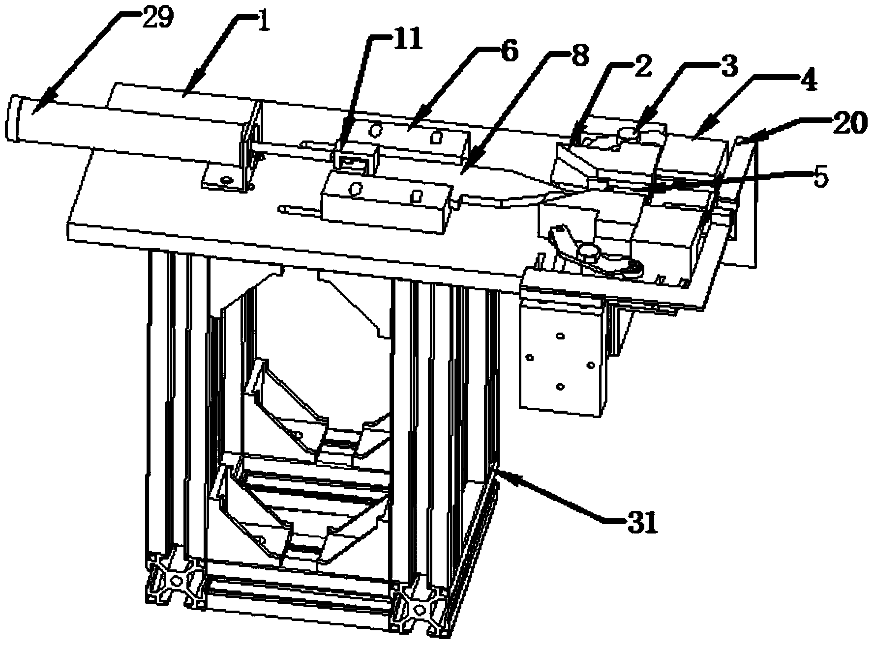
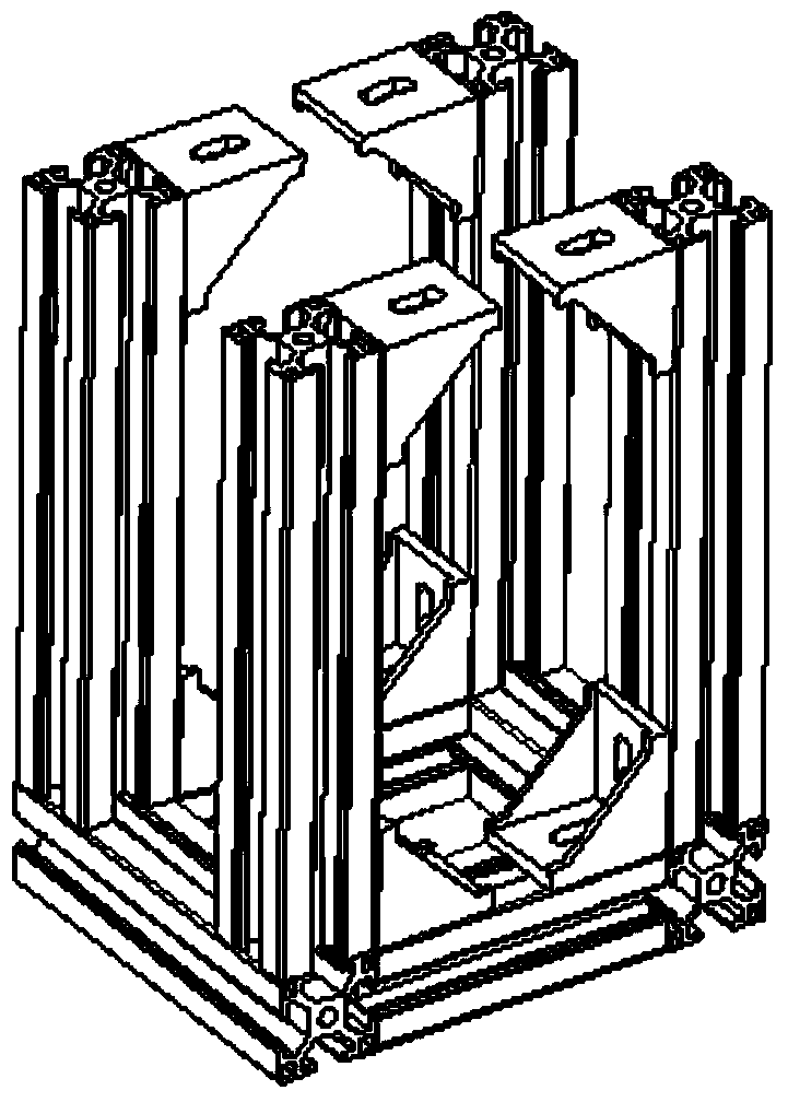
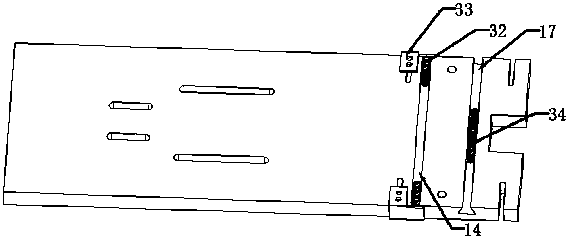
[0036] Referring to the accompanying drawings, the present invention includes a base 1, on which a push rod assembly is arranged, one end of the push rod assembly is provided with a push rod mechanism that drives the push rod assembly to move, and the other end of the push rod assembly is provided with Two sliders 2 that can slide longitudinally along the base, one side of each slider 2 is in contact with one end of the corner assembly that transmits the action force, and the other end of each corner assembly is in contact with the corner assembly that can move along the longitudinal direction of the base 1. The sliding guide groove block 4 contacts, and one end of the described guide groove block 4 is provided with the seedling setting assembly 20, and the outside of the two described slide blocks 2 is provided with a reset mechanism one, and a reset mechanism is provided between the two d...
PUM
 Abstract
Description
Claims
Application Information