
3D printing vehicle-mounted factory

A 3D printing and factory technology, applied in the field of 3D printing equipment, can solve the problems of insufficient product precision, inability to add additives, large optionality, etc., and achieve the effect of easy movement and portability, low cost, and space saving

Inactive Publication Date: 2015-02-04
中山喜来屋三维科技有限公司
View PDF4 Cites 4 Cited by
  • Summary
  • Abstract
  • Description
  • Claims
  • Application Information

AI Technical Summary

Problems solved by technology

[0003] The wire is composed of pure plastic, and the materials that can be drawn are limited, and pure materials cannot be added with additives, so they cannot meet the requirements of 3D printing products. Therefore, bar printing is mostly used now. The rod is thick and can be added with various additives. (such as glass fiber, nano-ceramic powder, etc.) to form composite materials with special functions, with large options, and even metal materials can be used, which can meet the high requirements of 3D printing products for materials, but the layer printed by rods is thicker. Therefore, the accuracy of the printed product is not high enough

Method used


Image

  • 3D printing vehicle-mounted factory
  • 3D printing vehicle-mounted factory
  • 3D printing vehicle-mounted factory

Examples


Embodiment Construction

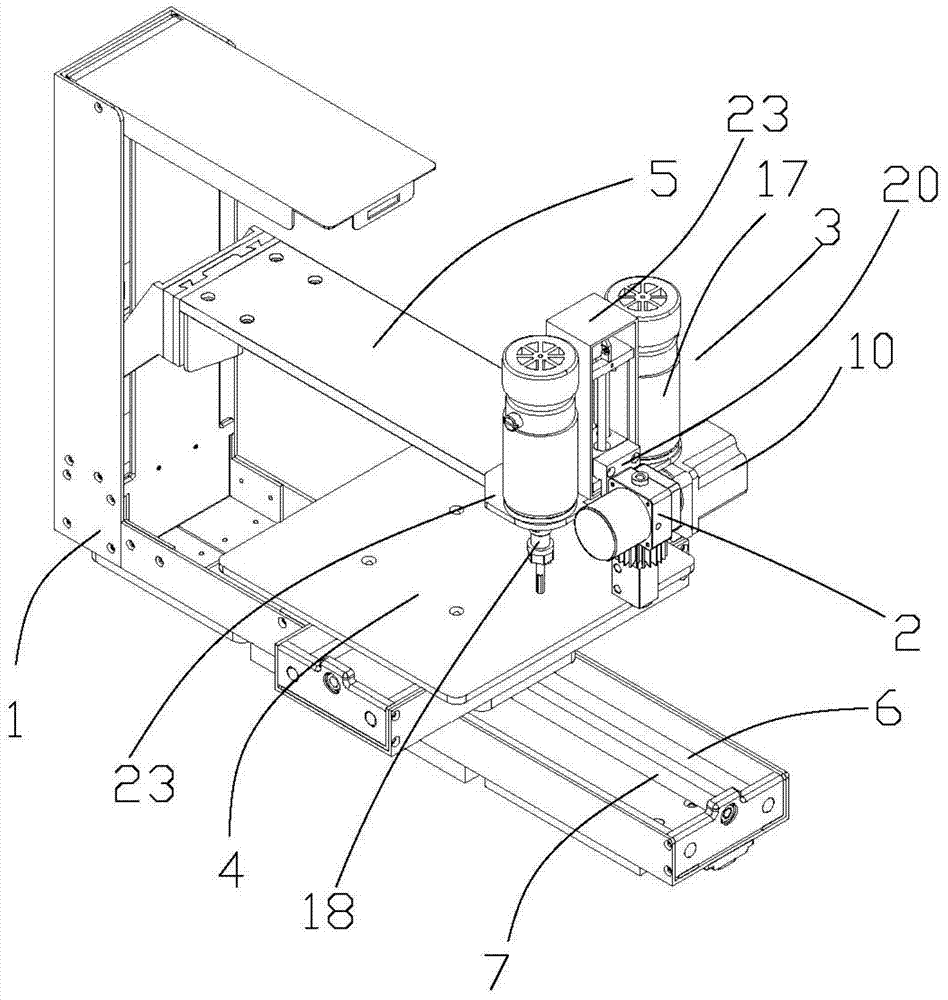
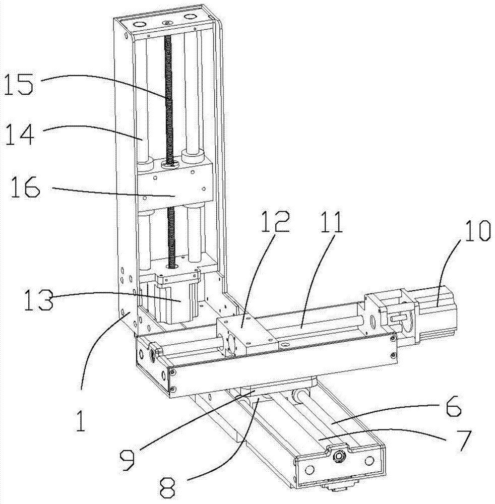
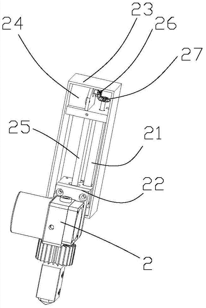
[0024] refer to Figure 1 to Figure 3 , the invention discloses a 3D printing vehicle-mounted factory, which mainly includes a CNC control center (not shown in the figure), a machine base 1, a printing head 2, a processing mechanism 3, a workbench 4, an X-axis moving mechanism, and a Y-axis moving mechanism. Moving mechanism and Z-axis moving mechanism.

[0025] The machine base 1 is composed of two mutually perpendicular square shells. The machine base 1 is an "L"-shaped structure as a whole, and one side of the shell is open. The X-axis moving mechanism is set in the bottom shell, and the Y-axis moving mechanism is set In the vertical casing, the above-mentioned structure makes full use of the internal space of the machine base 1, making the overall equipment more miniaturized.

[0026] The Y-axis moving mechanism is arranged on the X-axis moving mechanism, and the workbench 4 is arranged on the Y-axis moving mechanism, so that the workbench can be realized through the comb...


PUM


Abstract

The invention discloses a 3D printing vehicle-mounted factory which is characterized in that the factory contains a CNC control center, an engine base, a print head, a processing mechanism, a workbench, an X-axis movement mechanism, a Y-axis movement mechanism and an Z-axis movement mechanism; the X-axis movement mechanism and the Z-axis movement mechanism are arranged in the engine base; the Y-axis movement mechanism is arranged on the X-axis movement mechanism; the workbench is disposed on the Y-axis movement mechanism; a supporting arm is mounted on the Z-axis movement mechanism; the print head and the processing mechanism are arranged on the supporting arm; a lifting mechanism for lifting the print head is arranged between the print head and the supporting arm; and the X-axis movement mechanism, the Y-axis movement mechanism, the Z-axis movement mechanism, the lifting mechanism, the print head and the processing mechanism are all controlled by the CNC control center.

Description

technical field [0001] The invention relates to a 3D printing device, in particular to a vehicle-mounted factory with both 3D printing and processing. Background technique [0002] The current mainstream printing method is to use the printer to read the cross-sectional information of the pre-stored product, and then print these cross-sections layer by layer with melted raw materials. The raw materials are usually wire or rod. [0003] The wire is composed of pure plastic, and the materials that can be drawn are limited, and pure materials cannot be added with additives, so they cannot meet the requirements of 3D printing products. Therefore, bar printing is mostly used now. The rod is thick and can be added with various additives. (such as glass fiber, nano-ceramic powder, etc.) to form composite materials with special functions, with large options, and even metal materials can be used, which can meet the high requirements of 3D printing products for materials, but the layer...

Claims


Application Information

Patent Timeline
IPC IPC(8): B29C67/00
Inventor 王奉瑾戴雪青
Owner 中山喜来屋三维科技有限公司
Learn More