A swivel device and construction method of a small-span high-speed railway small-span bridge with a small angle

A small-angle, high-speed rail technology, applied in bridges, bridge construction, erection/assembly of bridges, etc., can solve the problems of complex manufacturing and processing of swivel devices, high precision requirements for structural rotation control, and large tonnage of bridge structures. The effect of construction efficiency, light weight and great economic benefits

Active Publication Date: 2016-04-13
CHINA RAILWAY SIYUAN SURVEY & DESIGN GRP
View PDF7 Cites 0 Cited by
  • Summary
  • Abstract
  • Description
  • Claims
  • Application Information

AI Technical Summary

Problems solved by technology

However, the existing swivel construction methods still have certain limitations: the existing swivel construction bridges are mainly in the form of long-span continuous girder bridges, rigid frame bridges, cable-stayed bridges, and arch bridges. The design is difficult and the construction period is long; secondly, because the existing swivel construction methods are all aimed at long-span bridges, the tonnage of the bridge structure itself is large, the manufacturing and processing technology of the swivel device is complicated, and the rotation control of the structure during the swivel construction process The precision requirement is high; third, the bridge structures targeted by the existing swivel construction methods mostly use single-span crossing lines

Method used


Image

  • A swivel device and construction method of a small-span high-speed railway small-span bridge with a small angle
  • A swivel device and construction method of a small-span high-speed railway small-span bridge with a small angle
  • A swivel device and construction method of a small-span high-speed railway small-span bridge with a small angle

Examples


Embodiment Construction

[0039] The present invention will be further described in detail below in conjunction with the accompanying drawings and specific embodiments.

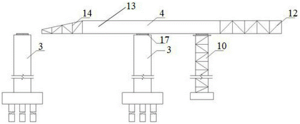
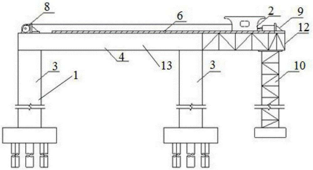
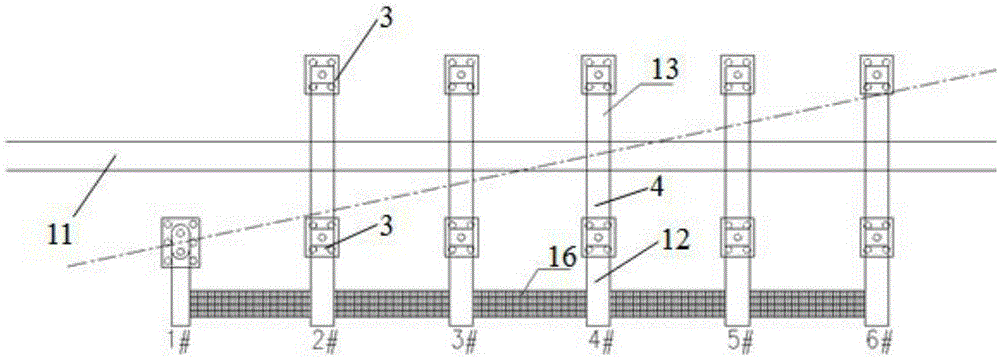
[0040] A swivel device for a small-span bridge that spans a high-speed rail at a small angle, such as Figure 1-2 As shown, the portal pier 1 includes the portal pier column 3 and the cover beam 4 on the portal pier column 3 arranged on both sides of the existing line 11, the portal pier 1 is arranged at intervals in parallel along the road length direction, and the road length direction That is, the length direction of the existing line 11, the main beam 2 is placed on the cover beam 4 along the length direction of the road. The cover beam 4 includes a cover beam body 13 and a back beam 12 connected to the rear of the cover beam body 13. A temporary pier column 10 is arranged on the outside of the portal pier column 3. The pier column 3 is on a straight line, and the back beam 12 is erected on the temporary pier column 10 . The des...


PUM


Abstract

The invention discloses a rotating device of a small-span bridge across a high-speed rail at a small angle. The bridge comprises portal piers and a main beam, wherein the portal piers cross an existing railroad, the main beam is arranged on the portal piers along the length direction of the railroad, the portal piers comprise portal pier columns arranged on both sides of the existing railroad and cover beams arranged on the portal pier columns, and the portal piers are arranged in parallel at intervals along the length direction of the railroad. The rotating device is characterized by comprising a chute, a sliding way, a spherical hinge support seat and a pushing device, wherein the chute is formed in the lower surface of the main beam along the longitudinal direction of the main beam, the sliding way is formed in the upper surfaces of the cover beams and corresponds to the chute, and the pushing device is used for enabling the main beam to move along the sliding way. The invention further provides a construction method of the rotating device which utilizes the small-span bridge across the high-speed rail at the small angle. The construction method comprises the steps of constructing the portal pier columns and the cover beams, placing the main beam, horizontally pushing the main beam, rotating the main beam and removing equipment. Stable rotation of the small-span bridge in the process of rotation can be realized, the construction difficulty is less, the construction time is short, the existing railroad is not influenced, and the total construction cost is reduced.

Description

technical field [0001] The invention relates to the technical field of bridge structures, in particular to a swivel device and a construction method for a small-span bridge spanning a high-speed railway at a small oblique angle. Background technique [0002] With the development of my country's railway construction, it often happens that new railways cross existing lines. When the oblique angle of the line is small, the crossing is generally realized in the form of a large-span T-structure or a cable-stayed bridge. In order to reduce the impact of these long-span bridge construction on the line as much as possible, the construction method is mostly swivel construction. [0003] At present, the swivel construction method for long-span bridges is becoming more and more mature, which has solved the difficult problem of span bridge construction to a large extent. The existing swivel construction method is generally as follows: a universal spherical joint is installed between t...

Claims


Application Information

Patent Timeline
Patent Type & Authority Patents(China)
IPC IPC(8): E01D21/08
CPCE01D21/08
Inventor 严爱国赵志军段鈜文功启耿杰林文泉俞浪林陶志列刘阳明傅彬
Owner CHINA RAILWAY SIYUAN SURVEY & DESIGN GRP
Why Eureka
Try Eureka