Front driver speed measuring device

A tachometer and precursor technology, which is applied to measurement devices, transmission parts, linear/angular velocity measurement, etc., can solve the problems of high-frequency vibration, affect the laser tracking effect, low measurement accuracy, etc., to compensate for coaxiality errors, avoid Vibration up and down and slippage from the shaft, the effect of high measurement accuracy

Active Publication Date: 2015-02-04
天津鼎成高新技术产业有限公司
View PDF6 Cites 3 Cited by
  • Summary
  • Abstract
  • Description
  • Claims
  • Application Information

AI Technical Summary

Problems solved by technology

In this method, because the transitional spline sleeve is light in weight and is not fixed with the transmission, when the output shaft is running at high speed, the transitional spline sleeve will

Method used


Image

  • Front driver speed measuring device
  • Front driver speed measuring device
  • Front driver speed measuring device

Examples


Embodiment Construction

[0014] In order to further understand the inventive content, features and effects of the present invention, the following examples are given, and detailed descriptions are as follows in conjunction with the accompanying drawings:

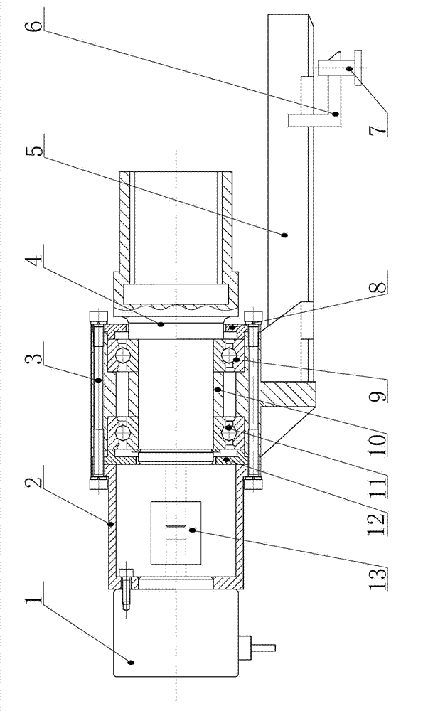
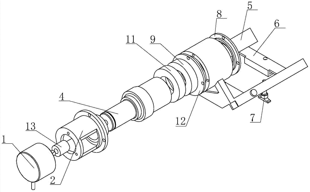
[0015] Such as figure 1 with 2 as shown,

[0016] A front-drive speed measuring device, including a bearing seat 3, in which a spline shaft 4 is installed through a rolling bearing. Specifically, two rolling bearings——bearing A 9 and bearing B—are arranged in the sleeve part of the bearing seat. 11. The two bearings are separated by a shaft sleeve 10. The right side of bearing A is positioned by the end cover A 8 installed on the bearing seat by bolts, and the right side of bearing B is positioned by the end cover installed on the bearing seat by bolts. B12 positioning,

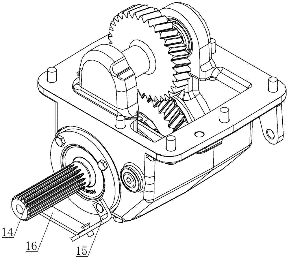
[0017] The front end of the spline shaft has a spline inner hole for spline connection with the front drive output shaft 14, the rear end of the spline shaft is connected with t...


PUM


Abstract

The invention relates to a front driver speed measuring device. The front driver speed measuring device comprises a bearing seat, wherein a spline shaft is arranged in the bearing seat through a rolling bearing; the front end of the spline shaft is provided with a spline inner hole which is connected with a front driver output shaft spline; the back end of the spline shaft is connected with a speed measuring encoder through an elastic shaft coupling; the speed measuring encoder is fixedly arranged on an encoder seat; the encoder seat is fixedly arranged at the back end of the bearing seat; a pair of transverse beams for mounting the front driver speed measuring device on a longitudinal beam of a front driver bracket is fixedly arranged at the lower end of the bearing seat; a tongue plate is arranged between the transverse beams; the tongue plate is provided with a locking bolt for fixing the tongue plate on a transverse beam of the front driver bracket. The front driver speed measuring device has the advantage that the revolving speed of a front driver output shaft can be measured accurately.

Description

technical field [0001] The invention belongs to the technical field of engineering machinery transmission test and testing, and in particular relates to a front drive speed measuring device. Background technique [0002] At present, laser sensors are used to detect the output speed of the transmission in China. The specific method is that the laser sensor installed on the sensor bracket tracks the single-tooth edge of the transition spline sleeve, and calculates the speed of the power output shaft of the transmission by calculating the number of pulses. . In this method, since the transitional spline sleeve is light in weight and is not fixed with the transmission, when the output shaft is running at high speed, the transitional spline sleeve will vibrate at high frequency, which directly affects the tracking effect of the laser. In addition, the laser sensor is greatly affected by the ambient temperature, and the measurement accuracy is low. Contents of the invention ...

Claims


Application Information

Patent Timeline
IPC IPC(8): F16H57/00G01P3/00
CPCF16H57/00G01P3/00
Inventor 郭海艳朴丕龙张彦杰郭晓震毛翠红
Owner 天津鼎成高新技术产业有限公司
Why Eureka
Try Eureka