
Iterative elimination method and system for interference between MIMO relay communication nodes

A relay node and relay communication technology, applied in the field of iterative elimination, can solve the problem that multi-antenna relay nodes cannot be directly applied, and achieve the effects of reducing symbol error rate, optimizing estimated value, and improving performance

Active Publication Date: 2015-02-04
SYSU CMU SHUNDE INT JOINT RES INST
View PDF3 Cites 4 Cited by
  • Summary
  • Abstract
  • Description
  • Claims
  • Application Information

AI Technical Summary

Problems solved by technology

However, these methods are only applicable to single-antenna relay nodes, and cannot be directly applied to relay nodes using multi-antenna technology, so that the current amplify-and-forward relay system with multiple antennas still cannot eliminate the relay well. interference between nodes

Method used


Image

  • Iterative elimination method and system for interference between MIMO relay communication nodes
  • Iterative elimination method and system for interference between MIMO relay communication nodes
  • Iterative elimination method and system for interference between MIMO relay communication nodes

Examples


Embodiment Construction

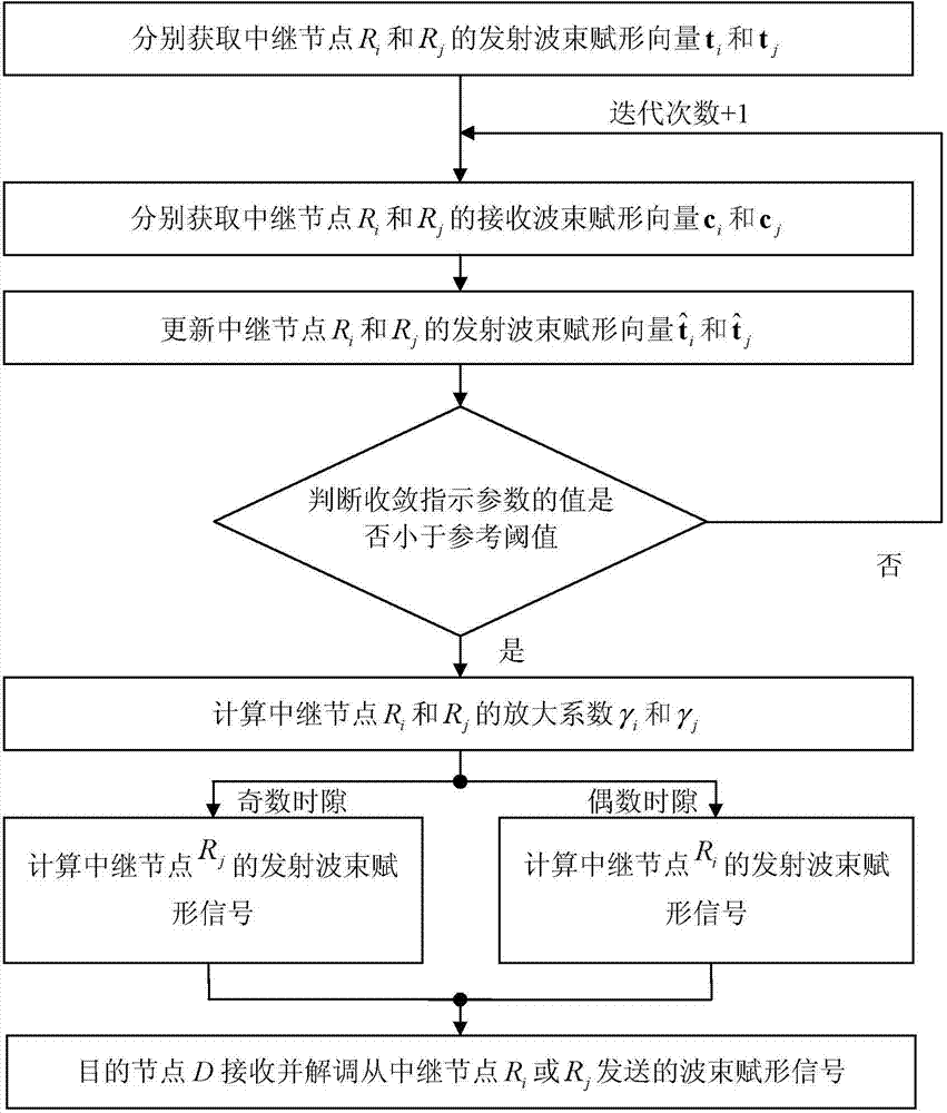
[0033] See picture 1. The present invention relates to a method for iterative elimination of interference between MIMO relay communication nodes, and its preferred embodiment includes the following steps:

[0034] Step A: via relay node R i Get relay node R i The transmit beamforming vector t i , and through the relay node R j Get relay node R j The transmit beamforming vector t j ;

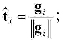
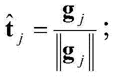
[0035] Specifically, according to the following formula I i and formula I j Calculate the relay node R i and R j The transmit beamforming vector t i and transmit beamforming vector t j , which can make the receiving power of the destination node D the maximum; where, the formula I i for

[0036] t ^ i = g i | | g i | | ; ...


PUM


Abstract

An iterative elimination method for interference between MIMO relay communication nodes includes: a step A of acquiring transmit beamforming vectors ti and tj; a step B of acquiring current reception beamforming vectors ci and cj; a step C of updating current transmit beamforming vectors t^i and t^j; a step D of determining whether a value of a convergence indication parameter is smaller than a reference threshold value, if no, returning to execute the step B, and if yes, executing a step E; the step E of obtaining amplification factors gammai and gammaj of relay nodes Ri, Rj; a step F of obtaining a transmit beamforming signal of the current odd time slot of the relay node Rj; a step G of obtaining a transmit beamforming signal of the current even time slot of the relay node Ri; and a step H of by a destination node D, receiving and demodulating the transmit beamforming signals. The above invention may inhibit IRI. The present invention also relates to a related system.

Description

technical field [0001] The invention relates to an iterative elimination method and system for interference between MIMO relay communication nodes. Background technique [0002] The MIMO (Multiple-Input Multiple-Output) system is a core technology used in communication standards such as LTE, WiMAX, and WiFi. It allows multiple antennas to simultaneously transmit and receive multiple spatial streams, and can distinguish distribution Signals to or from different spatial orientations. [0003] In the existing one-way relay technology, the two-way continuous relay technology in half-duplex mode can effectively improve the spectrum efficiency, thus becoming a very attractive system solution. A typical two-way continuous relay system includes a source node, a destination node D and two fixed relay nodes R 1 , R 2 , the source signal is received and forwarded alternately by two relay nodes. From the perspective of the source node, since the two relay nodes can be used to contin...

Claims


Application Information

Patent Timeline
IPC IPC(8): H04L25/03H04B7/15H04B7/04
Inventor 江明侯伟昆
Owner SYSU CMU SHUNDE INT JOINT RES INST
Learn More