Magnetic Sensing Loop for Rotor Position Sensing System of Rectifier Motor

A technology of rectifying motors and sensing systems, which is applied in the direction of using electric/magnetic devices to transfer sensing components, converting sensor outputs, measuring devices, etc., which can solve the problem of inability to ensure the slope and the inability to accurately determine the switch-type Hall sensor Switching points, limited sensor signal resolution, etc., to achieve an improved evaluation of the output signal

Inactive Publication Date: 2017-04-26
SCHAEFFLER TECH AG & CO KG
View PDF2 Cites 0 Cited by
  • Summary
  • Abstract
  • Description
  • Claims
  • Application Information

AI Technical Summary

Problems solved by technology

Of course, said sensors all have disadvantages
[0006] Consequently, the disadvantage of switching Hall sensors is that the motor cannot be positioned arbitrarily and the resolution of the sensor signal is only limited
High-resolution incremental sensors have the disadvantage that there is no correlation between the increments and the commutation point of the commutation motor after switching on the power supply
However, depending on the type of construction, a pole length of 9 mm is required
At the zero crossing of the output signal, a sufficient slope cannot be ensured in the known embodiment, so that the switching point of the switching Hall sensor cannot be accurately determined

Method used


Image

  • Magnetic Sensing Loop for Rotor Position Sensing System of Rectifier Motor
  • Magnetic Sensing Loop for Rotor Position Sensing System of Rectifier Motor
  • Magnetic Sensing Loop for Rotor Position Sensing System of Rectifier Motor

Examples


Embodiment Construction

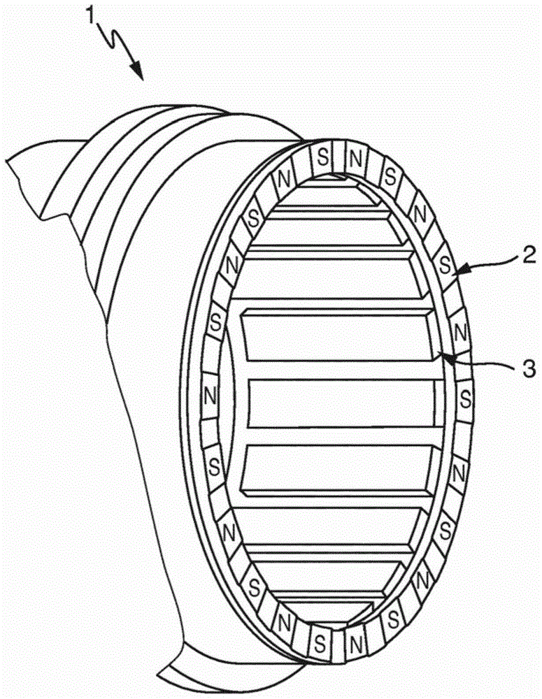
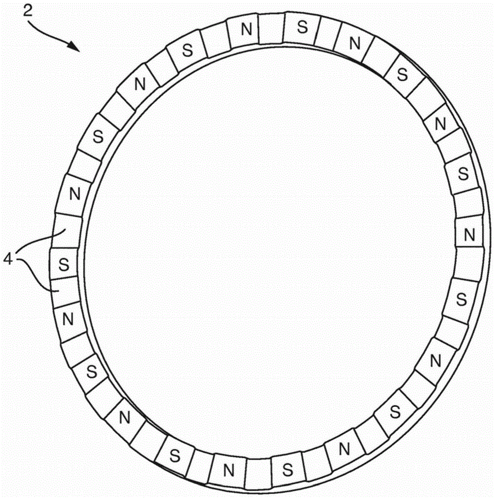
[0027] exist figure 1 The rotor 1 is shown in , which is designed as a hollow shaft. The rotor 1 of the commutated motor (not further shown) has, on the front side facing the sensor system arranged on the stator, a magnetic sensor ring 2 designed as a hollow cylinder with a predetermined number of magnetic poles N , S, the magnetic poles are arranged in an alternating manner. The magnetic poles N and S of the magnetic sensing ring 2 are arranged radially relative to the axis of the rotor 1 . A rotor magnet 3 is fastened within a rotor 1 designed as a hollow shaft, wherein the rotor magnet 3 has the same number of pole pairs N, S as the magnetic sensor ring 2 . The pole pair N, S is here formed by two magnetic poles N, S whose magnetization directions run in opposite directions. The number of rotor magnets 3 is preset by the rectifier motor, thereby also determining the number of magnetic poles N, S on the magnetic sensing ring 2 . Furthermore, a sensor system is to be unde...


PUM


Abstract

The invention relates to a magnetic transmitter ring of a rotor position sensing system of an electrically commutated motor, said transmitter ring being rotationally fixed to a rotor of the electrically commutated motor and having a specified number of magnetic poles with an alternating magnetizing direction. The aim of the invention is to produce a magnetic transmitter ring with which the commutation point can be reliably determined. This is achieved in that each magnetic pole pair has at least one indentation.

Description

technical field [0001] The invention relates to a magnetic sensing ring of a rotor position sensing system of a commutator motor, which is connected in a rotationally fixed manner to the rotor of a commutator motor and which comprises a predetermined number of magnets with alternating magnetization directions the magnet. Background technique [0002] Automatic clutches are increasingly being used in modern motor vehicles, especially passenger cars, as described in DE 10 2011 014 936 A1. The use of such a clutch has the advantage of improved driving comfort and results in the possibility of more frequent driving in gears with long transmission ratios. The clutches used here are used in hydraulic clutch systems, in which electrohydraulic actuators driven by commutator motors are connected to the clutch via hydraulic lines. [0003] DE 20 2006 008 962 U1 discloses a system for detecting the position of a rotor, which has a sensing structure which is mounted on the rotor and w...

Claims


Application Information

Patent Timeline
Patent Type & Authority Patents(China)
IPC IPC(8): G01D5/14
CPCG01D5/145
Inventor 马库斯·迪特里希约亨·金齐希
Owner SCHAEFFLER TECH AG & CO KG
Why Eureka
Try Eureka