Method for controlling the torque of an asynchronous machine

A technology for asynchronous motors and torque, applied in the control of generators, motor control, motor generator control, etc., can solve problems such as difficult identification

Active Publication Date: 2015-02-04
沃伊斯涡轮机有限公司
View PDF5 Cites 0 Cited by
  • Summary
  • Abstract
  • Description
  • Claims
  • Application Information

AI Technical Summary

Problems solved by technology

At the same time, however, model errors can only be identified very difficult

Method used


Image

  • Method for controlling the torque of an asynchronous machine
  • Method for controlling the torque of an asynchronous machine
  • Method for controlling the torque of an asynchronous machine

Examples


Embodiment Construction

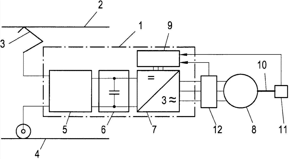
[0017] figure 1 An example of a traction drive of a rail vehicle is shown. The AC asynchronous electric machine 8 of the rail vehicle is controlled via the traction rectifier 1 with a voltage intermediate circuit inverter. Here, the voltage intermediate circuit 6 of the traction rectifier 1 is brought via the input circuit 5 to the voltage tapped off by the collector / brush 1 between the upper line 2 and the rail 4 . If necessary, the input circuit 5 converts the input voltage into a suitable DC voltage, which is fed to the inverter 7 on the voltage intermediate circuit 6 . The object here is to control the inverter 7 of the traction rectifier 1 with the regulating device 9 in such a way that an alternating voltage with variable amplitude and frequency is generated at the terminals of the asynchronous machine 8 in such a way that the asynchronous machine 8 The desired torque is generated on its shaft 10 both stably and dynamically. Here, under normal circumstances, the limi...


PUM


Abstract

The objective invention describes a method for controlling the torque of the asynchronous machine in the stator-fixed coordinate system without having to use a known flux model based on a voltage and current model. This is achieved by virtue of the fact that the stator flux step (deltapsiS(n+1)) to be carried out in the next scanning step (n+1) in order to achieve a desired torque and the rotor flux (psiR(n+1)) and stator flux (psiS(n+1)) for the next scanning step (n+1) are calculated in stator-fixed coordinates (alpha,beta) on the basis of the current rotor flux (psiR(n)) and stator flux (psiS(n)).

Description

technical field [0001] The invention relates to a method for regulating the torque of an asynchronous electric machine. Background technique [0002] Asynchronous motors operated via inverters are usually regulated according to the principle of field-oriented control. The basic idea of ​​field-oriented control is known to consider the electric machine in a coordinate system co-rotating with the magnetic flux, which coordinate system is oriented on the magnetic flux. The stator current can now be decomposed into a magnetic field-forming current component along the flux direction and a torque-forming current component perpendicular to the flux direction. The corresponding setpoint values ​​for the torque-forming and magnetic field-forming current components can be determined from the setpoint values ​​for the torque and the magnetic flux. In the simplest case, a proportional-integral (PI) controller is used respectively for each current component to determine the voltage spa...

Claims


Application Information

Patent Timeline
Patent Type & Authority Applications(China)
IPC IPC(8): H02P21/06
CPCH02P21/06H02P2021/0071H02P31/00
Inventor M·格拉斯尔
Owner 沃伊斯涡轮机有限公司
Why Eureka
Try Eureka