Multi-frequency emission beam formation method and application

A transmit beam and multi-frequency technology, applied in the field of multi-frequency transmit beamforming, can solve the problems of insufficient real-time performance of the cross array, shorten the time of three-dimensional acoustic images, and reduce the demand for calculations, etc.

Inactive Publication Date: 2016-01-20
ZHEJIANG UNIV
View PDF4 Cites 8 Cited by
  • Summary
  • Abstract
  • Description
  • Claims
  • Application Information

AI Technical Summary

Problems solved by technology

Aiming at the huge hardware overhead and computational load of the underwater 3D acoustic imaging system, as well as the insufficient real-time performance of the cross-shaped array, this method takes reducing the number of shots of the cross-shaped array as the starting point, and effectively reduces the number of shots of the cross-shaped array from the vertical beam The number of directions is reduced to the number of divided sectors, which greatly shortens the time required to construct a frame of three-dimensional acoustic images, solves the problem of insufficient real-time performance of the cross-shaped array to a certain extent, and can obtain a DM algorithm similar to that of a two-dimensional plane receiving array Similar beam performance indicators (main lobe width, side lobe peak value), while greatly reducing calculation requirements

Method used


Image

  • Multi-frequency emission beam formation method and application
  • Multi-frequency emission beam formation method and application
  • Multi-frequency emission beam formation method and application

Examples


Embodiment Construction

[0042] In order to describe the present invention in more detail, the method of the present invention will be described in detail below in conjunction with the drawings and specific embodiments.

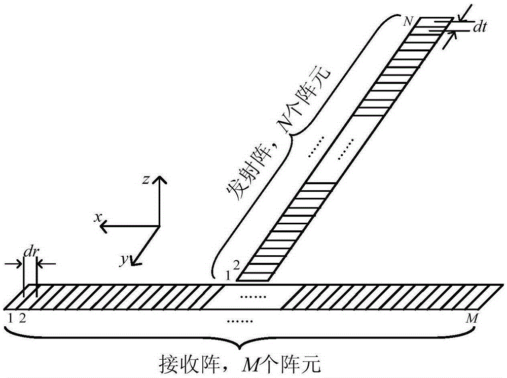
[0043] like figure 1As shown, the cross-shaped array is composed of two mutually perpendicular linear arrays. Wherein, the receiving array in the horizontal direction includes M array elements, the transmitting array in the vertical direction includes N array elements, and the distance between the receiving array and the transmitting array is respectively dr and dt. The cross-shaped array is on the xOy plane, and the intersection of the receiving array and the transmitting array is taken as the coordinate origin.

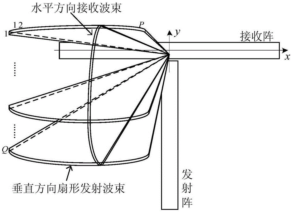
[0044] The cross-shaped array has the same three-dimensional acoustic imaging capability as the two-dimensional planar array. The main reason is that the cross-shaped array uses the transmitting and receiving arrays to perform beamforming in the vertical and horizontal di...


PUM


Abstract

The invention discloses a multi-frequency emission beam formation method. The method includes: (1) the beam direction of an emission array of a crossed array is divided into a plurality of sectors, a series of sector sonar beam signals of different frequencies are emitted in sequence in each sector, and the sector sonar beam signals with each frequency point to a beam direction in the corresponding sector; and (2) after the sector sonar beam signals with all the frequencies in each sector are emitted, sonar echo signals are received by employing a reception array in the crossed array, frequency information corresponding to all the sector sonar beam signals in each sector is extracted via discrete Fourier transform, beam formation calculation is performed in frequency domains corresponding to the frequency information, and a beam intensity result is obtained. According to the method, the emission time of the crossed array can be reduced, the beam performance similar to a two-dimensional plane reception array is obtained, and the complexity of an underwater real-time three-dimensional acoustic imaging system is reduced. The invention also discloses the application of the method in the reconstruction of three-dimensional acoustic images.

Description

technical field [0001] The invention relates to the field of three-dimensional acoustic imaging, in particular to a multi-frequency transmit beam forming method and application. Background technique [0002] Underwater real-time three-dimensional acoustic imaging technology is a new type of underwater detection technology that has received widespread attention in recent years. It has broad application prospects in many fields. [0003] Currently, there are three main three-dimensional acoustic imaging methods: focused acoustic imaging / acoustic lens focused imaging, beamforming acoustic imaging, and holographic acoustic imaging. Among them, the digital beamforming technology has the advantages of flexibility and high efficiency, so it is more and more widely used in the acoustic imaging system. [0004] In an underwater real-time 3D acoustic imaging system, in order to obtain 3D information of the scene, a 2D planar transducer array is usually required to receive sonar echo...

Claims


Application Information

Patent Timeline
Patent Type & Authority Applications(China)
IPC IPC(8): G01S17/89G01S7/483
CPCG01S17/89G01S7/483
Inventor 周凡沈斌坚刘雪松蒋荣欣陈耀武
Owner ZHEJIANG UNIV
Why Eureka
Try Eureka