Automatic oil deflector disassembly mechanism and oil press

A technology of automatic disassembly and oil retaining ring, applied in the direction of presses, manufacturing tools, etc., can solve problems such as difficulty in disassembly, and achieve the effects of labor saving, convenient operation and simple structure

Active Publication Date: 2015-02-11
GREE ELECTRIC APPLIANCES INC
View PDF6 Cites 0 Cited by
  • Summary
  • Abstract
  • Description
  • Claims
  • Application Information

AI Technical Summary

Problems solved by technology

When slag builds up on the oil deflector, disassembly will be very difficult, especially for women and the elderly

Method used


Image

  • Automatic oil deflector disassembly mechanism and oil press
  • Automatic oil deflector disassembly mechanism and oil press

Examples


Embodiment Construction

[0030] In order to make the purpose, technical solution and advantages of the present invention clearer, the oil retaining ring automatic disassembly mechanism and the oil press of the present invention will be further described in detail below in conjunction with the accompanying drawings and embodiments. It should be understood that the specific embodiments described here are only used to explain the present invention, not to limit the present invention.

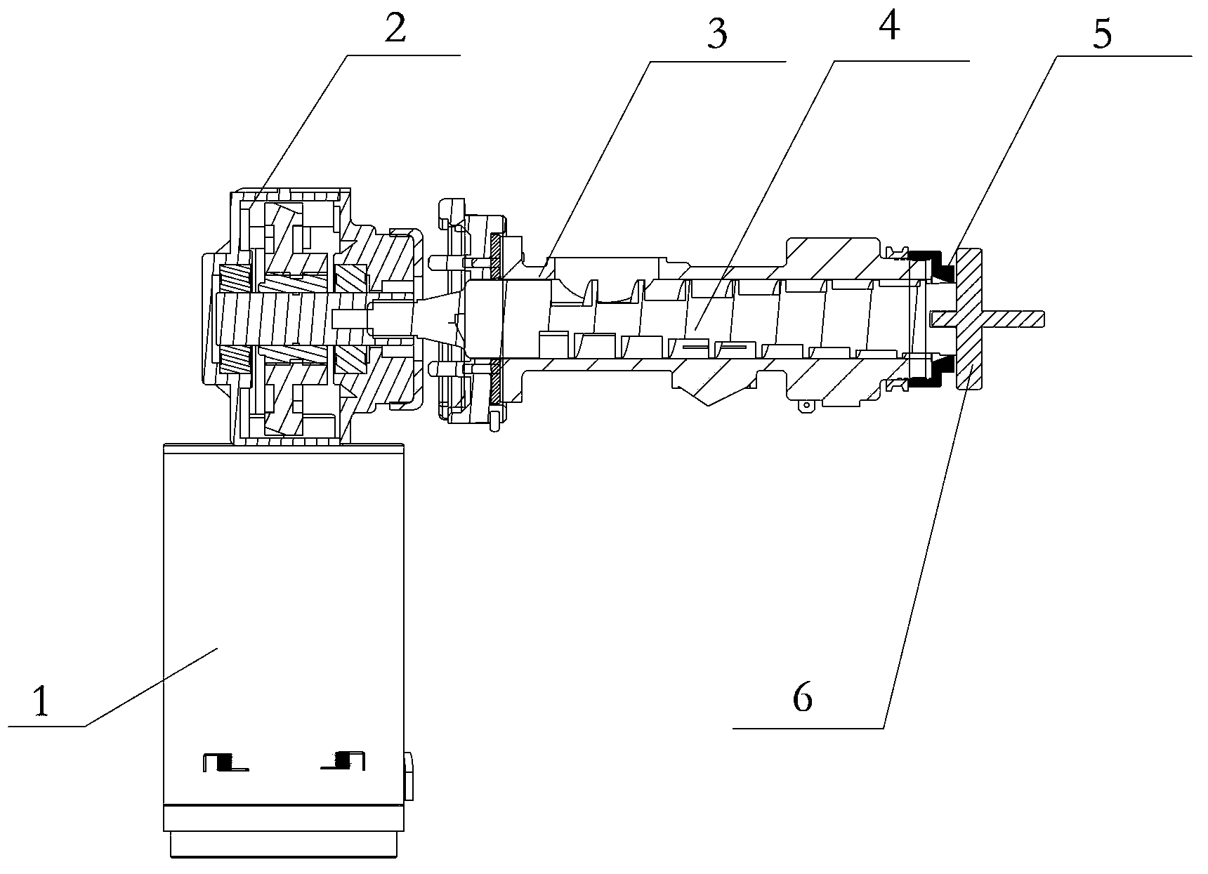
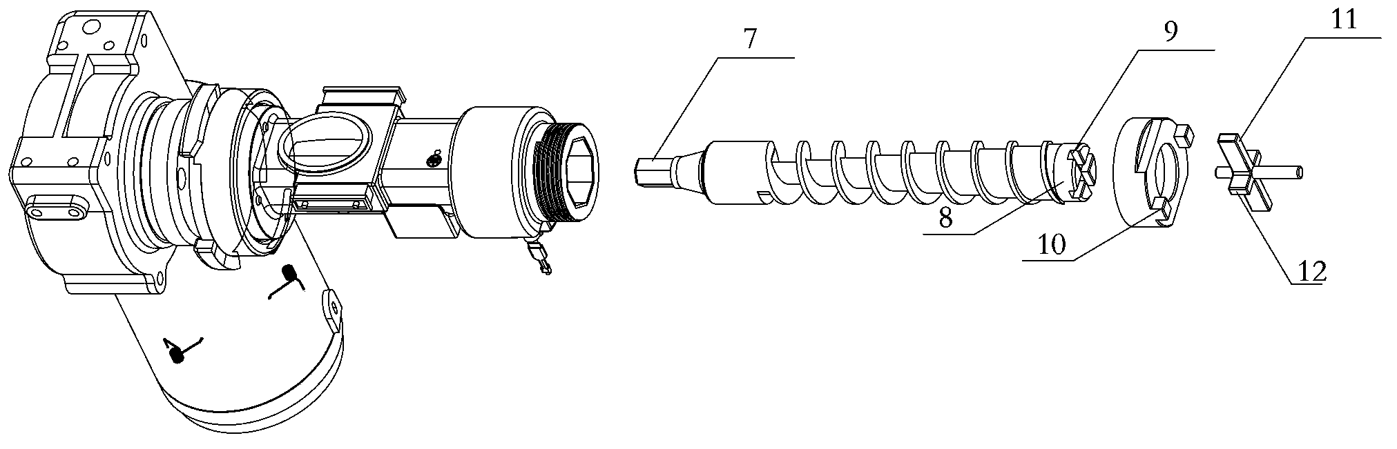
[0031] Such as figure 1 , 2 As shown, an automatic disassembly mechanism for an oil retaining ring, including: a motor 1, a reducer 2, a press chamber 3, a screw 4, an oil retaining ring 5 and a small wrench 6;

[0032] The drive connection of the input end of the motor 1 and the reducer 2;

[0033] The two ends of the screw 4 are the driving part 7 and the rotating part 8 respectively, and the output end of the reducer is connected to the driving part 7 through transmission;

[0034] The small wrench 6 is in transmissi...


PUM


Abstract

The invention provides an automatic oil deflector disassembly mechanism and an oil press. The automatic oil deflector disassembly mechanism comprises a motor, a speed reducer, a barrel, a screw, an oil deflector and a small spanner, the motor is in transmission connection with an input end of the speed reducer, a driving portion and a rotating portion are arranged at two ends of the screw respectively, an output end of the speed reducer is in transmission connection with the driving portion, the small spanner is in transmission connection with the rotating portion and driven by the screw to rotate, the motor drives the screw to rotate through the speed reducer, the barrel sleeves the screw, the oil deflector is connected with the barrel in a threaded manner, the small spanner is clamped on the oil deflector, and the small spanner drives the oil deflector to rotate relative to the barrel in a disassembled manner when rotating. The oil deflector can be automatically disassembled by the aid of reversal force of the motor, and the automatic oil deflector disassembly mechanism is simple in structure and convenient to operate, and labor is saved.

Description

technical field [0001] The invention relates to the technical field of food processing, in particular to an automatic detachment mechanism for an oil retaining ring and an oil press. Background technique [0002] With the development of science and technology and the continuous improvement of people's living standards, household oil presses have gradually penetrated into thousands of households. [0003] At present, in existing household oil presses, dismantling the oil retaining ring is an operation process that must be passed after each oil press. The oil retaining ring and the press chamber are threaded. When the oil press squeezes the raw materials, some of the raw materials are squeezed to the threaded connection between the oil retaining ring and the pressing chamber. At this time, it becomes very difficult to disassemble the oil retaining ring. It is inconvenient to use a wrench to manually unscrew the oil retaining ring at this time. When slag accumulates on the oi...

Claims


Application Information

Patent Timeline
IPC IPC(8): B30B15/00B30B9/12
Inventor 萧志根胡小帝陈冰孙娅丽覃德华丁泺火
Owner GREE ELECTRIC APPLIANCES INC
Why Eureka
Try Eureka