Variable valve timing control apparatus

Inactive Publication Date: 2015-02-11
AISIN SEIKI KK
View PDF6 Cites 2 Cited by
  • Summary
  • Abstract
  • Description
  • Claims
  • Application Information

AI Technical Summary

Problems solved by technology

[0006] Therefore, in the case where each of the most retarded angle phase and the most advanced angle phase, which are references for controlling the relative rotational phase, deviates or changes, the relative rotational phase cannot be properly controlled.

Method used


Image

  • Variable valve timing control apparatus
  • Variable valve timing control apparatus
  • Variable valve timing control apparatus

Examples


Embodiment Construction

[0025] Embodiments are described below. The embodiments are not limited to configurations including those described below, but may be changed or altered as appropriate.

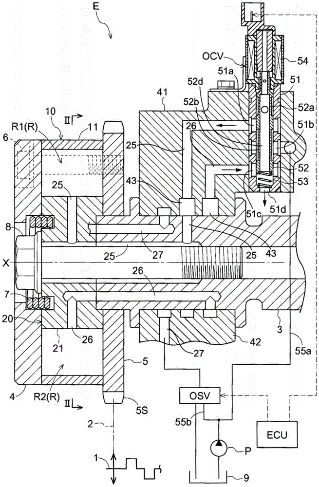
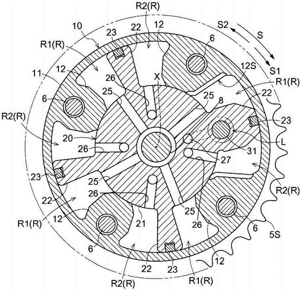
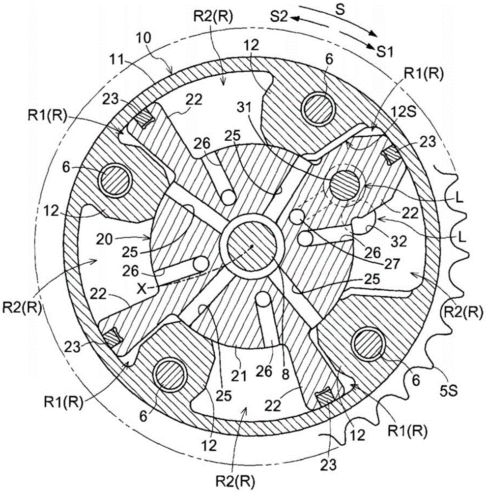
[0026] A first embodiment will be described with reference to the drawings. Such as figure 1 and figure 2 As shown, the valve opening and closing timing control device according to the first embodiment includes: an outer rotor 10 serving as a driving side rotating member; an inner rotor 20 serving as a driven side rotating member; and locking the relationship between the outer rotor 10 and the inner rotor 20 The relative rotation between the middle locking mechanism L. The outer rotor 10 rotates synchronously with a crankshaft 1 of an engine E serving as an internal combustion engine via a power transmission member 2 . The inner rotor 20 is connected to a camshaft 3 for opening and closing intake valves in the combustion chambers of the engine E. The inner rotor 20 is provided coaxially with a rotation ...


PUM


Abstract

A variable valve timing control apparatus includes a driving-side rotation member rotating in synchronization with a crankshaft of an internal combustion engine, a driven-side rotation member integrally rotating with a camshaft of the internal combustion engine, an intermediate lock mechanism being selectively switchable between a locked state and an unlocked state, a plurality of hydraulic chambers, at least one of the plurality of hydraulic chambers being positioned at a lower side than an axis of the camshaft, a plurality of partition portions, each of the plurality of partition portions dividing each of the hydraulic chambers into an advanced angle chamber and a retarded angle chamber, an electromagnetic valve including a supply and discharge port that is positioned at an upper side than the axis of the camshaft and switching supply and discharge of fluid relative to the hydraulic chambers, and a pump supplying fluid to the electromagnetic valve.

Description

technical field [0001] The present invention generally relates to a valve opening and closing period control device. Background technique [0002] There is known a valve timing control device for controlling a relative rotational phase of a driven-side rotary member relative to a drive-side rotary member that rotates synchronously with a crankshaft of an internal combustion engine, and may include an intermediate lock mechanism. The intermediate locking mechanism is configured to lock the aforementioned relative rotational phase at an intermediate phase within a range between the most retarded angle phase and the most advanced angle phase (ie, the intermediate locking mechanism is in a locked state). Such a valve opening and closing timing control device is disclosed in JP2011-256772A which will be referred to as Document 1 hereinafter. The valve opening and closing timing control device disclosed in Document 1 includes: a driven-side rotating member disposed coaxially with...

Claims


Application Information

Patent Timeline
IPC IPC(8): F01L1/34F01L9/02F02D13/02
CPCF16H25/08F01L1/3442F01L2001/0476F01L2001/3443Y10T74/2106
Inventor 弥永英臣小林昌树
Owner AISIN SEIKI KK
Why Eureka
Try Eureka