
Electric spraying type aviation gasoline engine

An aviation gasoline and engine technology, applied in engine components, engine control, machine/engine, etc., can solve the problems of difficult normal operation of the engine, poor fuel economy, difficult gasoline engine, etc., to improve cruising altitude, improve reliability, enhance The effect of overall strength

Active Publication Date: 2015-02-11
厦门林巴赫航空发动机有限公司
View PDF5 Cites 0 Cited by
  • Summary
  • Abstract
  • Description
  • Claims
  • Application Information

AI Technical Summary

Problems solved by technology

[0002] The mechanism that the existing aviation two-stroke gasoline engine provides the mixed gas to the cylinder is a carburetor. Although the technology of this kind of mechanism that uses the carburetor to provide the mixed gas is relatively mature, its problem is that the fuel economy is poor. In high-altitude areas, because the air is relatively thin, it is difficult for the carburetor to provide a mixture of precise concentrations to the cylinders of the engine, and it is difficult for the engine to work normally. Therefore, it is difficult for this traditional aviation two-stroke gasoline engine to be used in high-altitude areas.

Method used


Image

  • Electric spraying type aviation gasoline engine
  • Electric spraying type aviation gasoline engine
  • Electric spraying type aviation gasoline engine

Examples


Embodiment Construction

[0020] The present invention will be described in further detail below in conjunction with the accompanying drawings and specific embodiments.

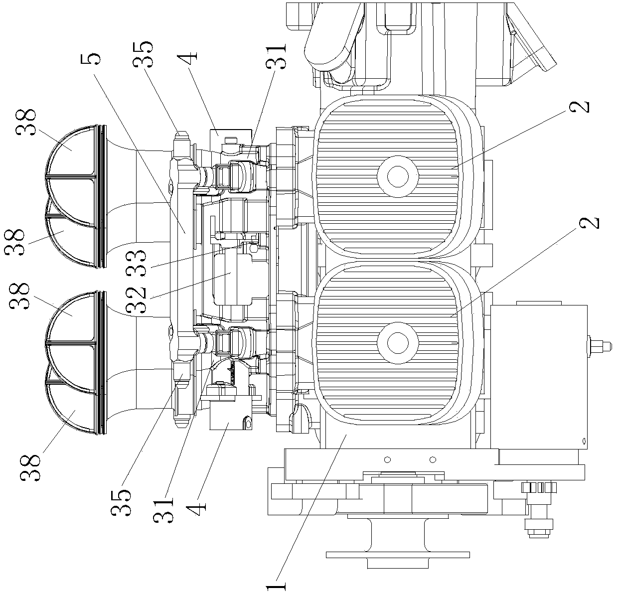
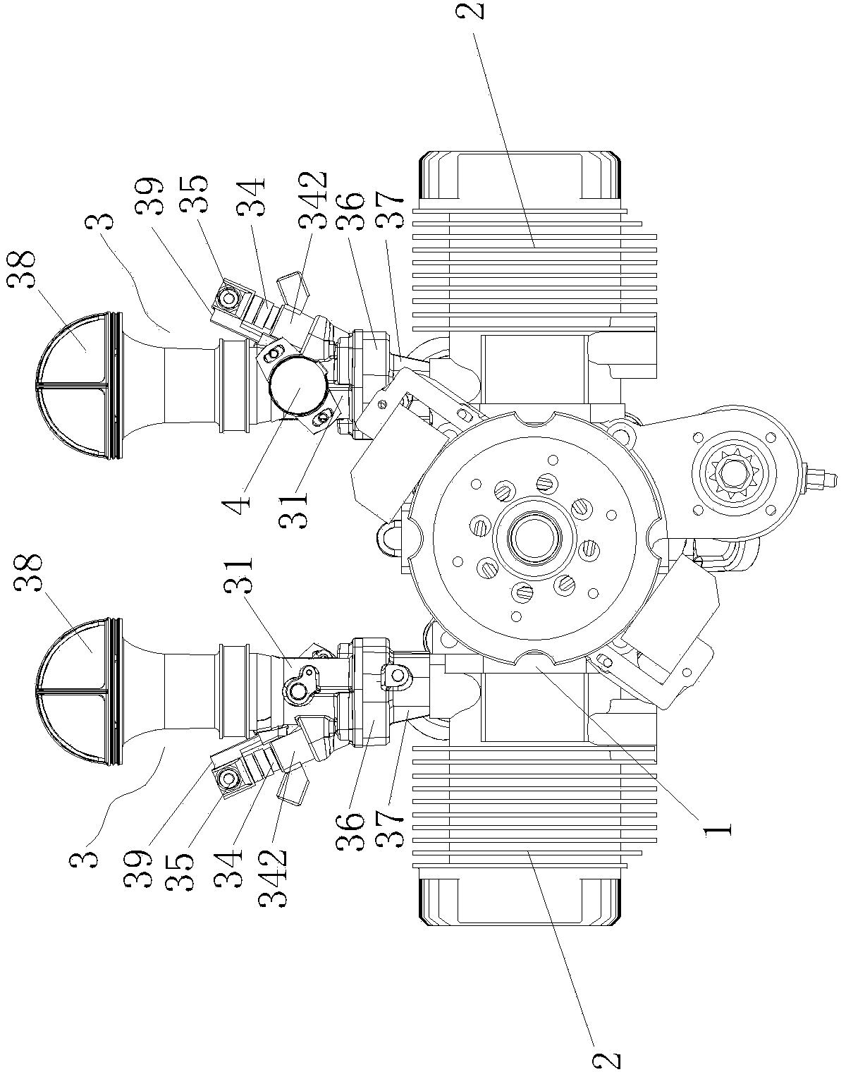
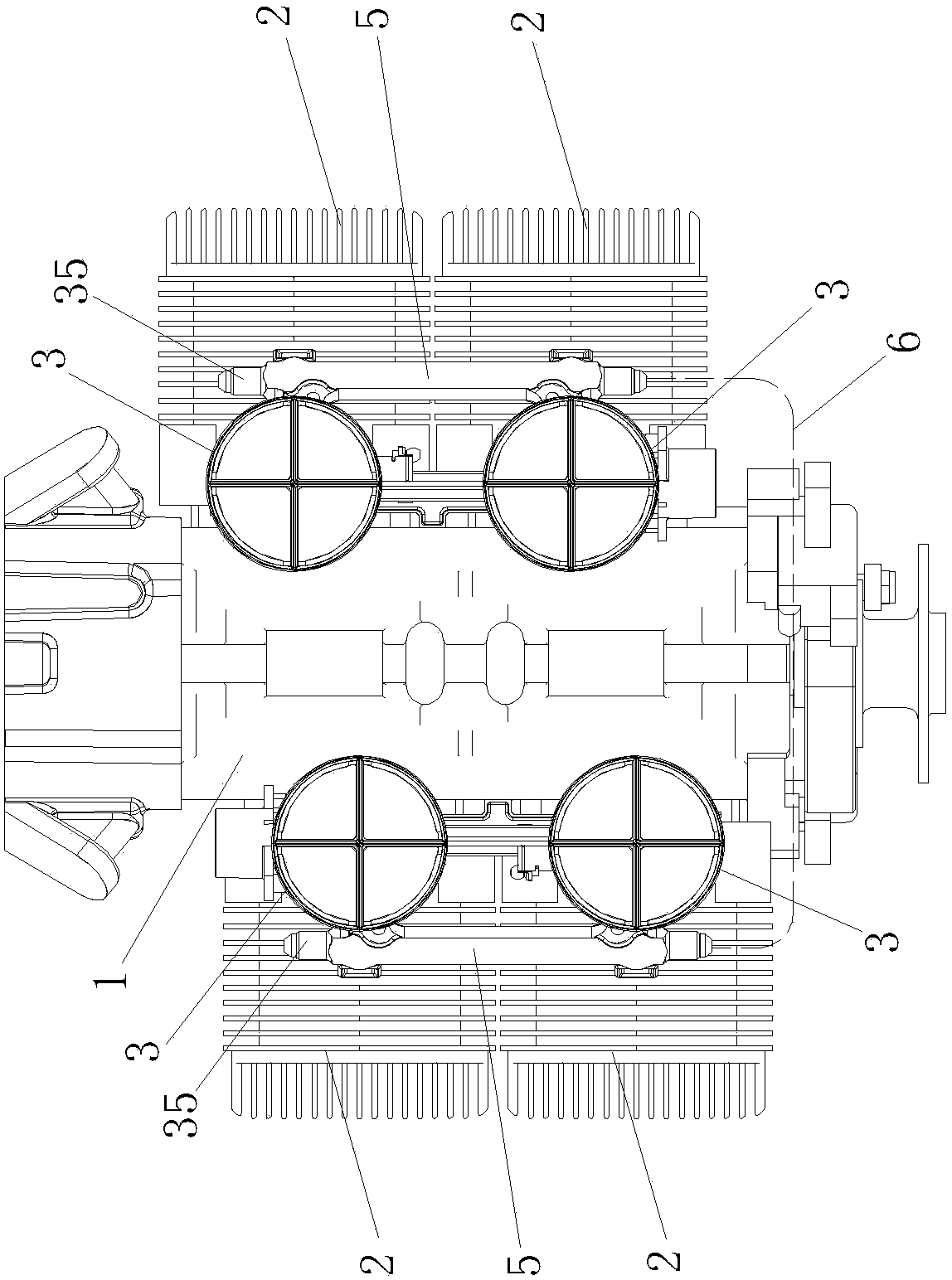
[0021] Figure 1 to Figure 6 Shown, a kind of electrospray type aviation gasoline engine comprises crankcase 1, four cylinder blocks 2, and four cylinder blocks 2 are contained in the both sides of crankcase 1 horizontally opposite in pairs, and the intake of four cylinder blocks 2 The air ports are all set upwards, and the air inlet of each cylinder block 2 is connected with an electric fuel injection mechanism 3, and the electric fuel injection mechanism 3 includes an intake pipe 31, a throttle shaft 32, a driving crank arm 33, a fuel injector 34, and an intake valve. The oil pipe 35 and the throttle shaft 32 are arranged in the middle of the intake pipe 31 along the radial direction of the intake pipe 31. The part where the throttle shaft 32 is located in the inner hole of the intake pipe 31 is fixedly connected with a throttle, an...


PUM


Abstract

The invention discloses an electric spraying type aviation gasoline engine, which comprises a crankcase and four cylinder bodies, wherein the two cylinder bodies are arranged at two sides of the crankcase in pairwise parallel opposite arrangement, an air inlet of each of the four cylinder bodies is in upward arrangement, an electric spraying mechanism is connected onto the air inlet of each cylinder body, each electric spraying mechanism comprises an air inlet pipe, a throttle valve rotating shaft, a driving crank arm, an oil sprayer and an oil pipe, the throttle valve rotating shaft is arranged in the middle part of the air inlet pipe in the radial direction of the air inlet pipe in a penetrating way, the part, positioned in an inner hole of the air inlet pipe, of the throttle valve rotating shaft is fixedly connected with a throttle valve, one end, positioned outside the air inlet pipe, of the throttle valve rotating shaft is fixedly connected with the driving crank arm, the oil sprayer is arranged at the side surface of the air inlet pipe in a way of being inclined to the axial line of the air inlet pipe, the lower part of the oil sprayer is provided with a spray nozzle, the middle part of the oil sprayer is provided with an electromagnetic switch valve, the upper part of the oil sprayer is connected with the oil inlet pipe, the spray nozzle is positioned in the inner hole of the air inlet pipe and the lower part of the throttle valve, the lower part of the air inlet pipe is fixedly connected with a flange, and the upper part of the air inlet pipe is connected with an air filter. The electric spraying type aviation gasoline engine has the advantages that the application range is wider, and the fuel oil economical performance is better.

Description

technical field [0001] The invention relates to the technical field of manufacturing aviation gasoline engines, in particular to an electronic injection type aviation gasoline engine. Background technique [0002] The mechanism that the existing aviation two-stroke gasoline engine provides the mixed gas to the cylinder is a carburetor. Although the technology of this kind of mechanism that uses the carburetor to provide the mixed gas is relatively mature, its problem is that the fuel economy is poor. In high-altitude areas, because the air is relatively thin, it is difficult for the carburetor to provide a precise concentration of mixed gas to the cylinders of the engine, and it is difficult for the engine to work normally. Therefore, it is difficult for this traditional aviation two-stroke gasoline engine to be used in high-altitude areas. Contents of the invention [0003] The technical problem to be solved by the present invention is to provide an electric injection typ...

Claims


Application Information

Patent Timeline
Patent Type & Authority Applications(China)
IPC IPC(8): F02D41/30F02M51/00
Inventor 陈聪明
Owner 厦门林巴赫航空发动机有限公司
Learn More