A vibration energy control system and method

A vibration energy and control system technology, applied in the direction of control of mechanical energy, electric components, gas-hydraulic dampers, etc., can solve problems such as poor vibration control effect and energy waste

Active Publication Date: 2016-04-06
重庆桐雨石科技有限公司
View PDF6 Cites 0 Cited by
  • Summary
  • Abstract
  • Description
  • Claims
  • Application Information

AI Technical Summary

Problems solved by technology

[0005] In view of this, the present invention provides a vibration energy control system and method to solve the problem of poor vibration control and energy waste in the energy outflow vibration control method in the prior art, and energy waste in the energy outflow vibration control method. The problem

Method used


Image

  • A vibration energy control system and method
  • A vibration energy control system and method
  • A vibration energy control system and method

Examples


Embodiment 1

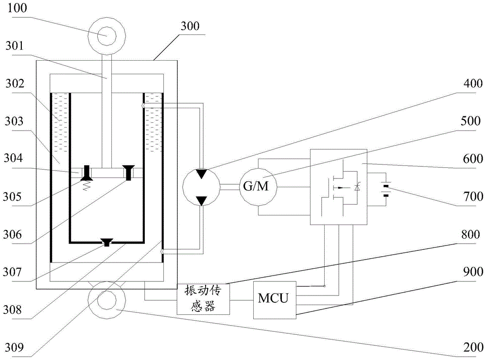
[0075] see figure 1 , which shows a schematic structural view of a vibration energy control system provided by the present invention, including: an upper connection head 100, a lower connection head 200, and a vibration system 300, wherein the vibration system 300 specifically includes: a piston rod 301, Compressed gas 302, hydraulic oil 303, piston 304, piston overflow valve 305, piston check valve 306, inner cylinder check valve 307, inner cylinder 308 and outer cylinder 309.

[0076] Specifically in this embodiment, the upper connector 100 is connected to one end of the piston rod 301, the other end of the piston rod 301 is equipped with a piston 304, and the piston overflow valve 305 and the piston check valve 306 are arranged on the piston 304; The valve 307 is installed at the bottom of the inner cylinder 308; the outer cylinder 309 is concentrically installed on the outside of the inner cylinder 308; the outer cylinder 309 is connected with the lower connector 200; hydr...

Embodiment 2

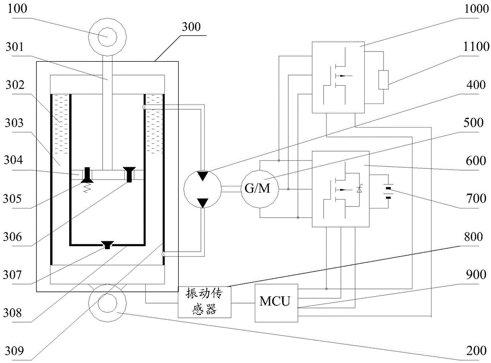
[0114] Based on the above examples, please refer to image 3 , which shows another structural schematic diagram of a vibration energy control system provided by the present invention, which also includes: a rectifier 1000 electrically connected to the generator motor 500, and an energy consumption resistor 1100 connected in series with the rectifier 1000. Wherein, the MCU 900 is also connected to the rectifier 1000 .

[0115] At this time, the MCU 900 is used to control and adjust the control angle of the bidirectional converter 600 when the current vibration force generated by the vibration system 300 is greater than the maximum generating damping force under the joint action of the battery 700 and the energy dissipation resistor 1100, so that the control angle of the bidirectional converter 600 is Driven by electric energy, the generator motor 500 is controlled to generate a damping force to offset the vibration force; when the current vibration force generated by the vibrat...


PUM


Abstract

The invention provides a system and a method for controlling vibration energy. When vibration force currently generated by a vibration system is not larger than the maximum electricity generation damping force under the action of a storage battery, the vibration energy is utilized to drive an oil pump oil motor to drive a generator motor to act, the generator motor is in an electricity generation state and charges the storage battery; and when the vibration force currently generated by the vibration system is larger than the maximum electricity generation damping force under the action of the storage battery, electric energy in the storage battery is utilized to drive and control the generator motor to generate vibration damping force so as to offset the vibration force. Therefore, the vibration energy is converted into the electric energy to be stored in the storage battery, the energy is reused, further, when the vibration energy is larger, the electric energy in the storage battery can be utilized to drive and control the generator motor to generate the vibration damping force to offset the vibration force, and compared with a scheme that external energy is required to be introduced to generate the vibration damping force in the prior art, the energy is saved.

Description

technical field [0001] The invention relates to the technical field of vibration reduction control, and more specifically, to a vibration energy control system and method. Background technique [0002] Vibration widely exists in the movement of objects. For example, when a car is running, the excitation generated by the uneven road surface is transmitted to the car body through the wheels, causing the car body to vibrate and affecting the comfort, safety and maneuverability of the car. Since vibration is an unbalanced energy form, in order to achieve the purpose of vibration reduction, existing vibration energy control methods mainly include energy outflow vibration control methods and energy inflow vibration control methods. [0003] Among them, the energy outflow vibration control method refers to that the vibration energy is drawn out of the vibration system, for example, the damping shock absorber installed between the car body and the wheel is to convert the mechanical ...

Claims


Application Information

Patent Timeline
Patent Type & Authority Patents(China)
IPC IPC(8): F16F9/06F03G7/08H02K7/00
CPCF03G7/08F16F9/06H02K7/00
Inventor 李川倪茂飞陈旭东喻其炳陈志强冯鑫
Owner 重庆桐雨石科技有限公司
Why Eureka
Try Eureka