Bulb lamp structure

A technology for lamp holders and lamp holders, applied in point light sources, lighting and heating equipment, electric light sources, etc., can solve the problems of non-automatic implementation, high production cost, and small lighting range, and achieve good heat dissipation effect and high heat dissipation efficiency High, wide-range effect

Inactive Publication Date: 2015-02-11
MAINHOUSE (XIAMEN) ELECTRONICS CO LTD
View PDF11 Cites 2 Cited by
  • Summary
  • Abstract
  • Description
  • Claims
  • Application Information

AI Technical Summary

Problems solved by technology

In addition, the chip 3' of this LED bulb is placed flat on the upper end of the lamp holder 2', and its irradiation direction is mainly concentrated on the top of the bulb, so it also has the problem of a small lighting range.
Furthermore, since the circuit board and the chip 3' are connected through the connecting wire 5', such an arrangement does not utilize automatic implementation. Therefore, the current LED bulbs have limited production capacity and high production costs.

Method used


Image

  • Bulb lamp structure
  • Bulb lamp structure
  • Bulb lamp structure

Examples


Embodiment Construction

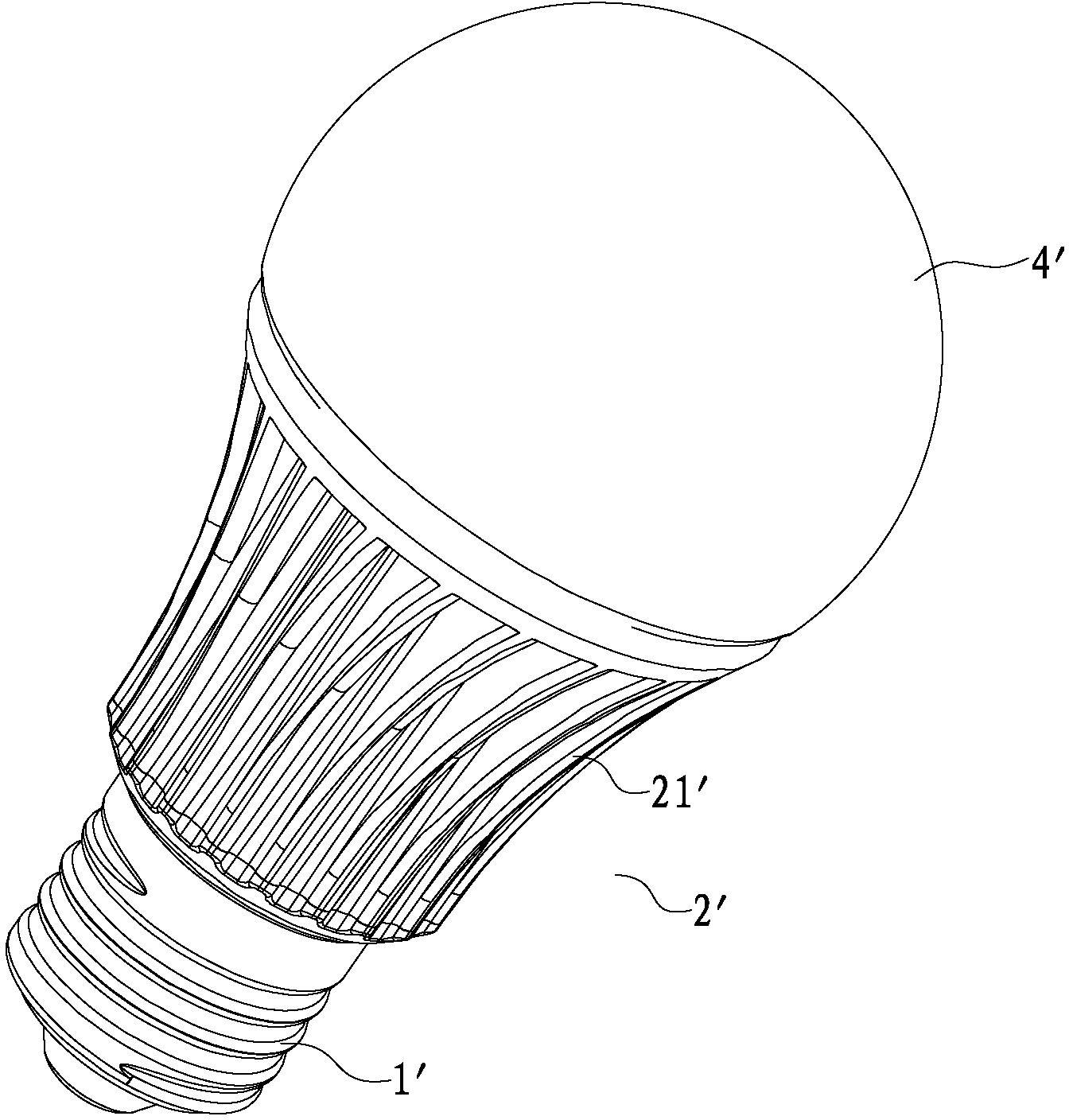
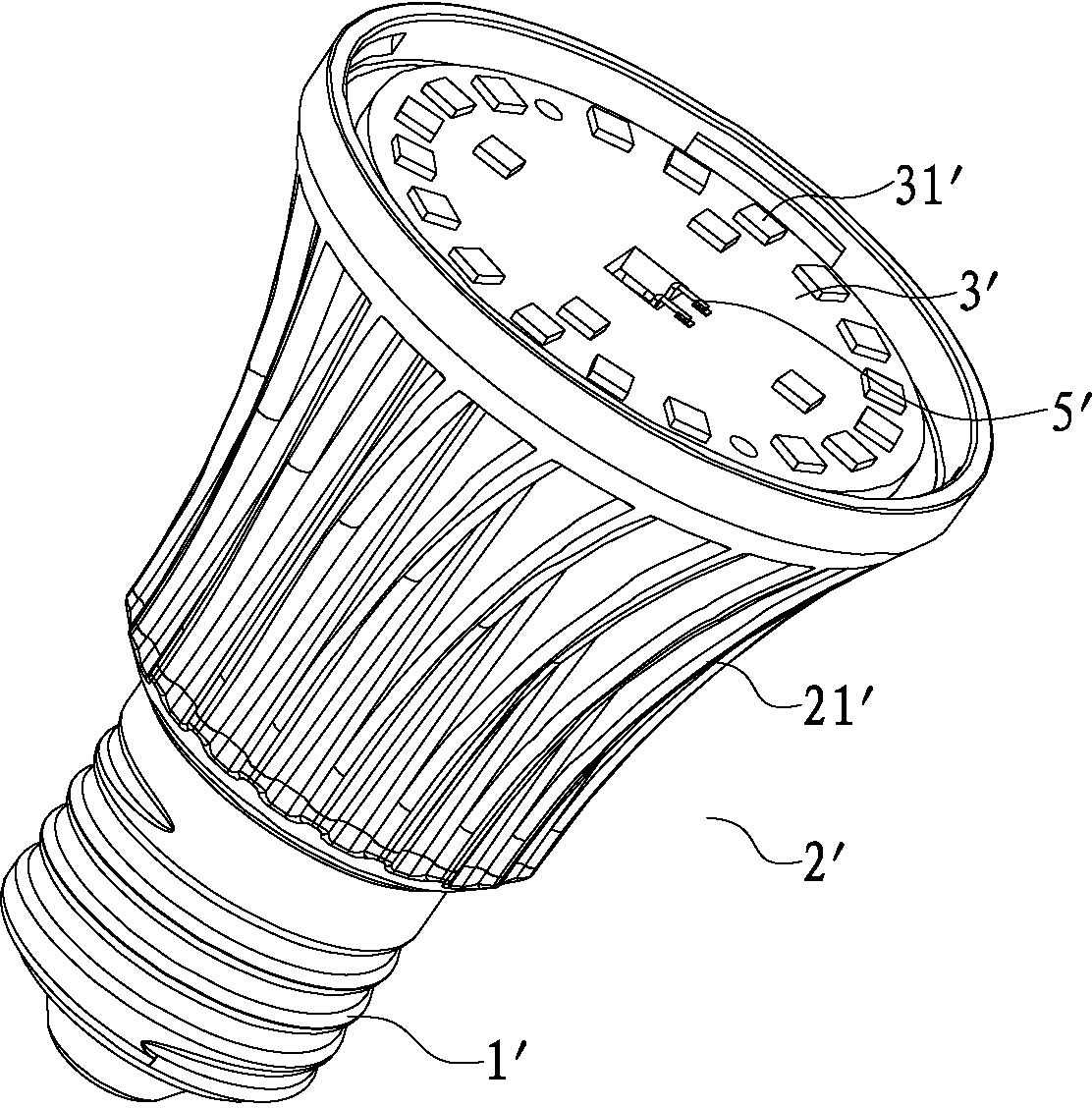
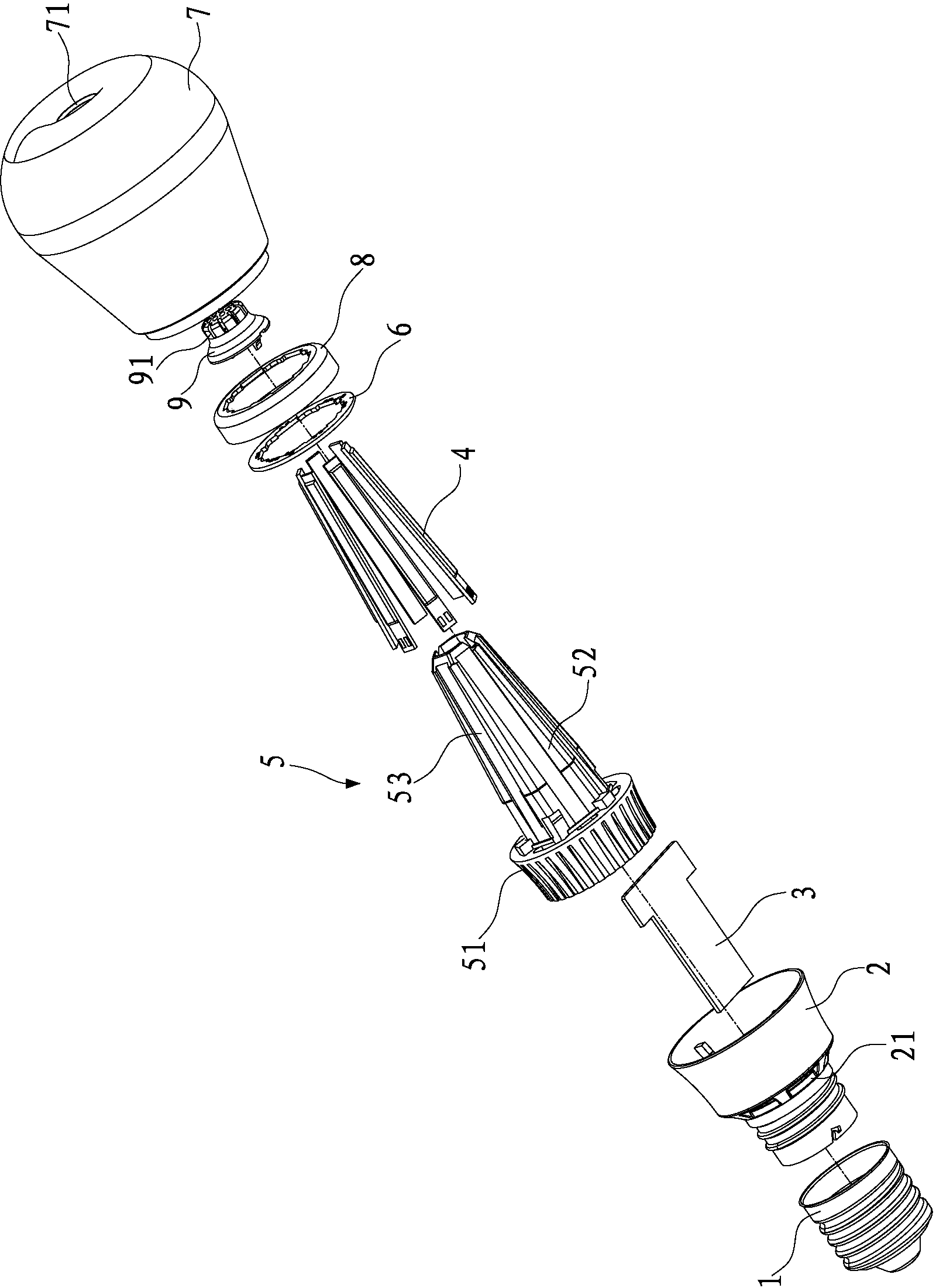
[0019] like Figure 3 to Figure 6 As shown, the present invention discloses a light bulb structure, which includes a lamp base 1, a lamp holder 2, a circuit board 3 for driving LED chips to work, several chips 4 with LED lamp beads distributed thereon, a heat sink 5, a A double-sided board 6 connecting the chip 4 and the circuit board 3 , and a bulb 7 .

[0020] The lamp cap 1 is matched with the lower end of the lamp holder 2, and the lamp holder 2 is provided with an air inlet. In this embodiment, an air inlet 21 is distributed on the lower edge of the lamp holder 2 adjacent to the lamp holder 1, and the lower part of the radiator 5 forms a ring shape. The cover base 51 fits in the lamp base 2, and the upper end of the ring-shaped cover base 51 extends upward at intervals with several sheet-shaped substrates 52, each sheet-shaped substrate 52 encloses a chamber 53, and the chamber 53 is from bottom to top Form a tapered state, so that the upper end of the chamber 53 is form...


PUM


Abstract

The invention discloses a bulb lamp structure which comprises a lamp socket, a lamp holder, a circuit board, a bulb shell, a plurality of chips, a radiator and a double-sided board, wherein the lamp holder is matched with the lamp socket; the circuit board is used for driving the LED chips to work; the bulb shell covers the chips to be matched with the lamp holder; the chips are distributed with LED lamp beads; the double-sided board is used for connecting the chips with the circuit board; the lower end edge, adjacently connected with the lamp socket, of the lamp holder is provided with an air inlet; the lower part of the radiator forms a ring-shaped cover seat to be matched in the lamp holder; a plurality of sheet substrates upwards extend from the upper end of the ring-shaped cover seat at interval; a cavity is defined by the sheet substrates in a surrounding manner; the lower part of the cavity is communicated with the air inlet of the lamp holder; the circuit board is longitudinally arranged in the lamp holder; the chips are respectively matched on the outer surfaces of the sheet substrates; and an air outlet which is exactly aligned to the top end of the radiator is arranged at the center of the top end of the bulb shell. The bulb lamp structure is not only capable of well solving the junction temperature radiating problem of the LED bulb lamp chips, but also capable of effectively realizing the large irradiation angle, and is beneficial for automatic production.

Description

technical field [0001] The invention relates to a lighting device, in particular to a bulb structure imitating a traditional incandescent lamp with LED as a light source. Background technique [0002] LED is made of electroluminescent semiconductor material, which has excellent characteristics such as low voltage, high efficiency, good monochromaticity, strong applicability, good stability, short response time, long life, and no pollution to the environment; Widely used in lighting, decoration and other fields, a LED bulb based on LED chips came into being. An important difference between this kind of LED bulb and traditional incandescent bulbs is that the luminous body in the bulb is replaced by the LED chip. substitute. [0003] like figure 1 , 2 As shown, the structure of the common LED light bulbs currently on the market includes a lamp base 1', a lamp base 2' connected to the lamp base 1' as a heat sink, a circuit board located in the lamp base 2', and a circuit boar...

Claims


Application Information

Patent Timeline
IPC IPC(8): F21S2/00F21V29/508F21Y101/02
CPCF21K9/20F21Y2101/00
Inventor 周南庆吴荣奎
Owner MAINHOUSE (XIAMEN) ELECTRONICS CO LTD
Why Eureka
Try Eureka