Graph pattern decomposition method adopting triple patterning photoetching technology

A technology of triple exposure and photolithography technology, which is applied in special data processing applications, instruments, electrical digital data processing, etc., and can solve problems such as the decline in chip yield

Active Publication Date: 2015-02-11
FUDAN UNIV
View PDF5 Cites 7 Cited by
  • Summary
  • Abstract
  • Description
  • Claims
  • Application Information

AI Technical Summary

Problems solved by technology

How to assign the GDSII design layout patterns to multiple different masks, so that the pattern conflicts on the same mask are the least, is the key to the multi-exposure layout allocation method; at the same time, in order to reduce the number of conflicts, the same layout pattern may It will be divided and assigned to different masks, and the division points on the same pattern are called stitches; practice shows that too many stitches will lead to a decrease in chip yield

Method used


Image

  • Graph pattern decomposition method adopting triple patterning photoetching technology
  • Graph pattern decomposition method adopting triple patterning photoetching technology
  • Graph pattern decomposition method adopting triple patterning photoetching technology

Examples


Embodiment 1

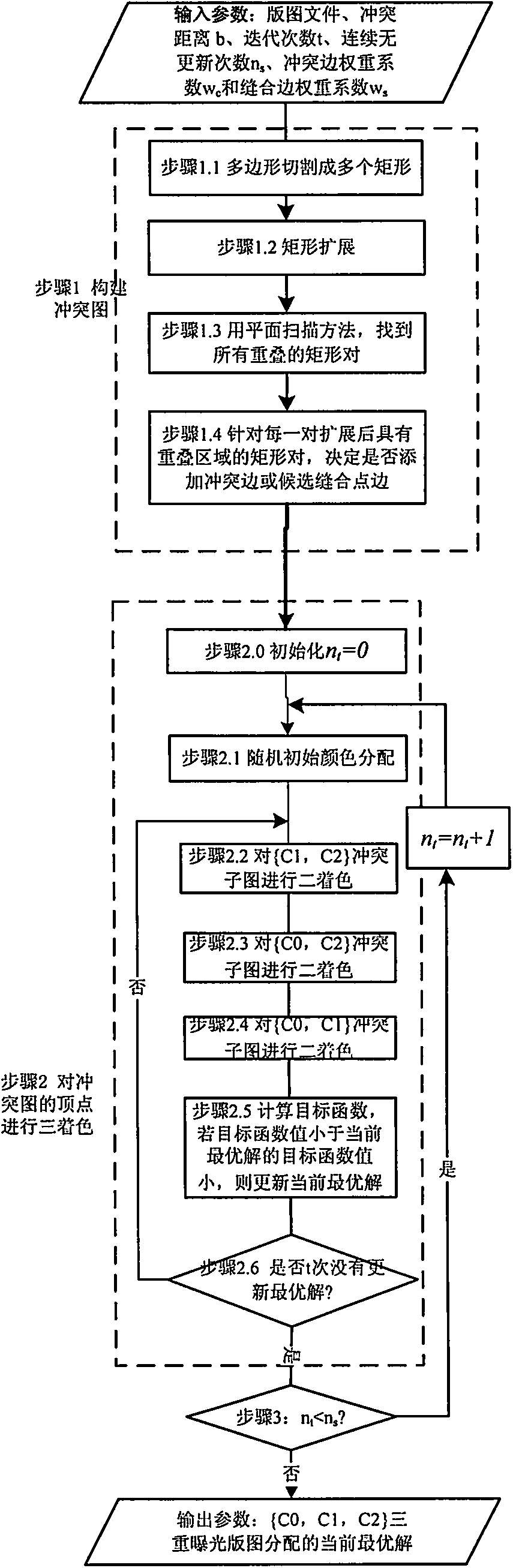
[0072] The pattern in the input layout file is as Figure 7 As shown, it needs to be triple-exposure layout pattern assignment. Among them, 1, 2, 3, and 4 are polygon layout patterns. Set the number of iterations n s = 30, the number of consecutive no updates t = 3, the conflict edge weight coefficient w c =10, seamed edge weight coefficient w s =1.

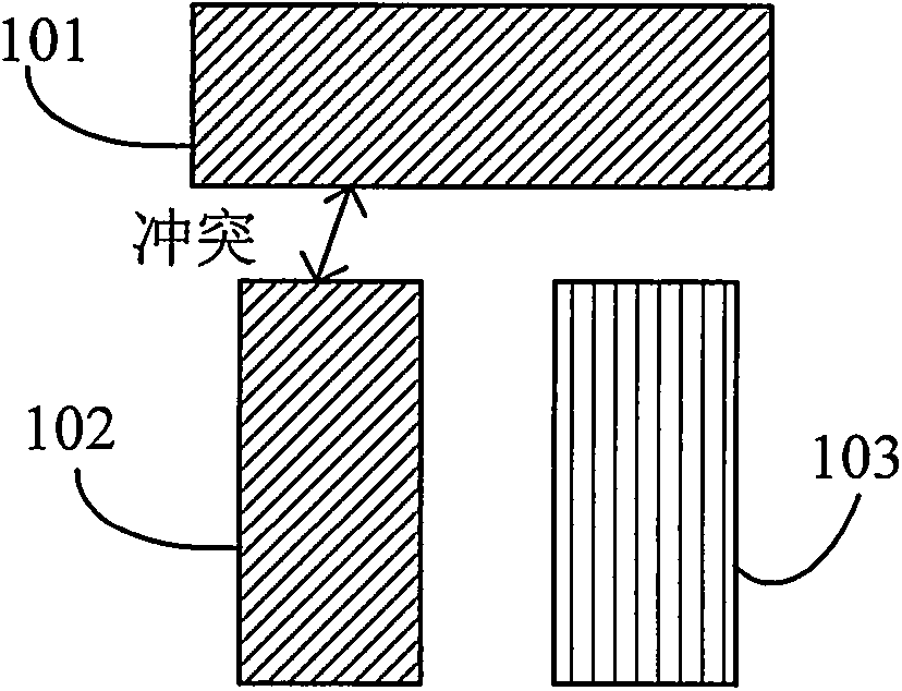
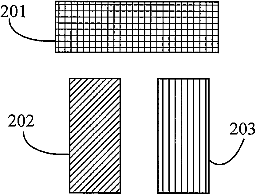
[0073] As described in step 1.1, the Figure 7 The polygon in is cut into several rectangles, such as Figure 8 shown. Among them, polygon 2 is cut into rectangle 21 and rectangle 22 , and polygon 4 is cut into rectangle 41 and rectangle 42 . According to step 1.2, expand the sides of each rectangle outward by b / 2, and then construct the conflict graph according to the methods described in steps 1.3 to 1.4. The result is as follows Figure 8 As shown in , where the rectangles are expressed as vertices in the conflict graph, the solid lines indicate that there are conflicting edges between the rectangles, and the edge weig...

Embodiment 2

[0085] The method of the present invention is realized with C++ programming language, and runs on a 64-bit 2.66GHz CPU and a linux machine with 4GB memory. The test layout comes from the layout of the first metal layer in the ISCAS-85&89 test case. Set conflict distance b=160nm, conflict edge weight coefficient W c =10, seamed edge weight coefficient W s = 1, the number of iterations n s =30, continuous no update times t=3; Experimental results are as shown in table 1, wherein #C, #S, COST, imp represent respectively the number of conflicts after decomposing the layout with the method of the present invention, stitching point number, objective function and the present invention The COST improvement ratio compared to the corresponding method. Compared with two methods in prior art document [8] and document [9], the improvement effect of the present invention's method can reach 29% and 42.2% the highest respectively (improvement effect is defined as: (COST of other methods-th...


PUM


Abstract

The invention belongs to the field of design for manufacturability of semiconductor photoetching technologies, and particularly relates to a graph pattern decomposition method adopting a triple patterning photoetching technology. The method comprises steps of firstly, establishing a conflict graph through a rectangle expansion method, then randomly producing a three-colored initial solution, fixing one color in each turn of optimization, performing two-colored optimization on a conflict sub-graph of the rest two colors through a double patterning pattern distribution method, repeating the iterative optimization process until the current optimum solution is not undated for multiple times, and finally, repeatedly calling the above steps and selecting an optimal three-colored result as an output result. According to method, the existing double patterning pattern distribution method is adopted, an optimal strategy obtained through multiple computation is adopted, and a globally optimal solution is searched, so that the purpose of distributing a graph pattern through the triple patterning photoetching technology is realized.

Description

technical field [0001] The invention belongs to the field of manufacturability design of semiconductor lithography process, and specifically relates to a layout pattern decomposition method of triple exposure lithography process. In this method, dense layout patterns are distributed to three different masks, which can meet the requirements of semiconductor Photolithography process requirements. Background technique [0002] The prior art discloses that the photolithography process is one of the key processes in the integrated circuit manufacturing process. As the feature size of integrated circuits continues to shrink, the layout pattern density continues to increase, but the wavelength of the light source used in lithography has not been significantly reduced, and the exposure resolution has not been significantly improved, resulting in pattern conflicts on the same mask. ) is increasing in number. The pattern conflict is defined as a distance between two layout patterns ...

Claims


Application Information

Patent Timeline
Patent Type & Authority Applications(China)
IPC IPC(8): G06F17/50G06F9/44
Inventor 曾璇陆伟成周海严昌浩张业
Owner FUDAN UNIV
Why Eureka
Try Eureka