
Device for an electrically driven rail vehicle

A rail vehicle, electric drive technology, applied in electric vehicles, AC induction motor traction, motor vehicles, etc., can solve the problems of space consumption, difficulty in the limit value of interference current, affecting the overall efficiency of the traction unit, etc., and achieves low structural consumption. Effect

Inactive Publication Date: 2015-02-11
SIEMENS MOBILITY GMBH
View PDF8 Cites 7 Cited by
  • Summary
  • Abstract
  • Description
  • Claims
  • Application Information

AI Technical Summary

Problems solved by technology

According to the state of the art, grid chokes are difficult and space-consuming due to the high demands on disturbance current limit values ​​in most DC railway grids
Losses occurring in the DC grid choke considerably affect the overall efficiency of the traction unit

Method used


Image

  • Device for an electrically driven rail vehicle
  • Device for an electrically driven rail vehicle
  • Device for an electrically driven rail vehicle

Examples


Embodiment Construction

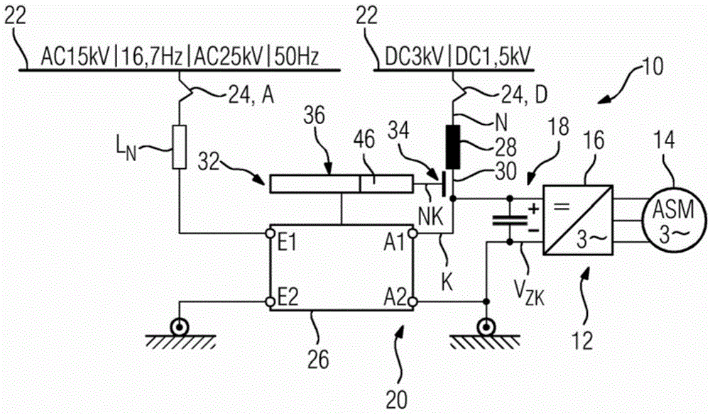
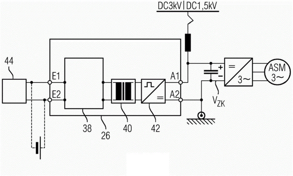
[0034] figure 1 A schematic diagram of an electrical circuit 10 of a rail vehicle is shown. The electrical circuit 10 includes a traction unit 12 for generating torque to drive the rail vehicle in a traction mode of the rail vehicle. In particular, the traction unit has a traction motor 14 designed as an asynchronous machine, which is mechanically coupled to a drive shaft (not shown in detail) of the rail vehicle. The traction unit 12 also has a power supply unit 16 which is designed to provide the electrical power required for the operation of the traction motor 14 . The power supply unit is designed in particular as a pulse inverter which, based on the DC voltage VZK of the intermediate circuit 18 , generates an AC current for operating the traction motor 14 by means of switching processes of switching elements or switching valves. For example, the switching element or the switching valve can be configured as an IGBT (Insulated Gate Bipolar Transistor, insulated gate bipol...


PUM


Abstract

The invention relates to a device for an electrically driven rail vehicle, comprising a circuit assembly (20), which can be connected to a traction unit (12) of the rail vehicle and - for the operation of the traction unit - to a railway network supply (22), an alternating-voltage mode, in which the circuit assembly (20) is connected to the railway network supply (22), which carries an alternative voltage, and a direct-voltage mode, in which the circuit assembly (20) is connected to the railway network supply (22), which carries a direct voltage, wherein the circuit assembly (20) has an active multipole (26), which is connected between the railway network supply (22) and the traction unit (12) as a voltage transforming device in the alternating-voltage mode, and has a compensation device (32), which, in the direct-voltage mode, is designed to counteract a noise component of a network current (N) drawn from the railway network supply (22) or generated by the traction unit (12) and flowing to the railway network supply (22). According to the invention, in order to provide a device for electrically driven rail vehicles that have an active multipole for operation in the alternating-voltage module, by means of which device a noise current compensation function can be implemented in the direct-voltage mode with little complexity, the compensation device (32) comprises at least one sensor unit (34) for detecting at least one network current characteristic (NK), the active multipole (26), and a control unit (36), which control unit is designed to control the active multipole (26) in dependence on the network current characteristic (NK).

Description

technical field [0001] The invention relates to a device for an electrically driven rail vehicle having a circuit arrangement which can be connected to a traction unit of the rail vehicle and which—for operating the traction unit—is supplied with electricity from a railway network device connection; an alternating voltage mode, in which the circuit arrangement is connected to a railway grid power supply, which conducts an alternating voltage; and a direct voltage mode, in which the circuit arrangement is connected to A rail network supply connection, which conducts a direct voltage, wherein the circuit arrangement has active multipoles, which are connected as a transformer in alternating voltage mode between the rail network supply and the traction unit , and the circuit arrangement has a compensating device which, in the DC voltage mode, is set up for counteracting the grid current drawn from the railway grid supply or generated by the traction unit and flowing to the railway...

Claims


Application Information

Patent Timeline
IPC IPC(8): B60L9/00B60L9/18B60L9/24H02M1/12B60L9/30H02M1/10H02J1/02H02M1/15
CPCB60L2200/26B60L9/18H02M1/10B60L9/30B60L9/24Y02T10/7241B60L2210/40B60L2270/147H02M7/23H02M3/285B60L2210/10Y02T10/7216B60L9/005B60L2210/30H02M2007/4835Y02T10/72H02M7/4835
Inventor 马丁·格林卡
Owner SIEMENS MOBILITY GMBH
Learn More