
Hydraulic control valve assemblies and control systems for water networks

A technology of hydraulic control system and hydraulic control valve, applied in the direction of control/regulation system, auxiliary non-electric fluid pressure control, fluid pressure control, etc., can solve the problems of cost increase, cost increase, maintenance cost increase, etc., and achieve enhanced modules effect

Inactive Publication Date: 2016-09-07
AVK HLDG AS
View PDF4 Cites 0 Cited by
  • Summary
  • Abstract
  • Description
  • Claims
  • Application Information

AI Technical Summary

Problems solved by technology

Furthermore, as more complex control functions are performed, the disorganized structure results in increased costs in production because the individual components must be produced and assembled individually, and the cost of ownership increases due to increased maintenance costs

Method used


Image

  • Hydraulic control valve assemblies and control systems for water networks
  • Hydraulic control valve assemblies and control systems for water networks
  • Hydraulic control valve assemblies and control systems for water networks

Examples


Embodiment Construction

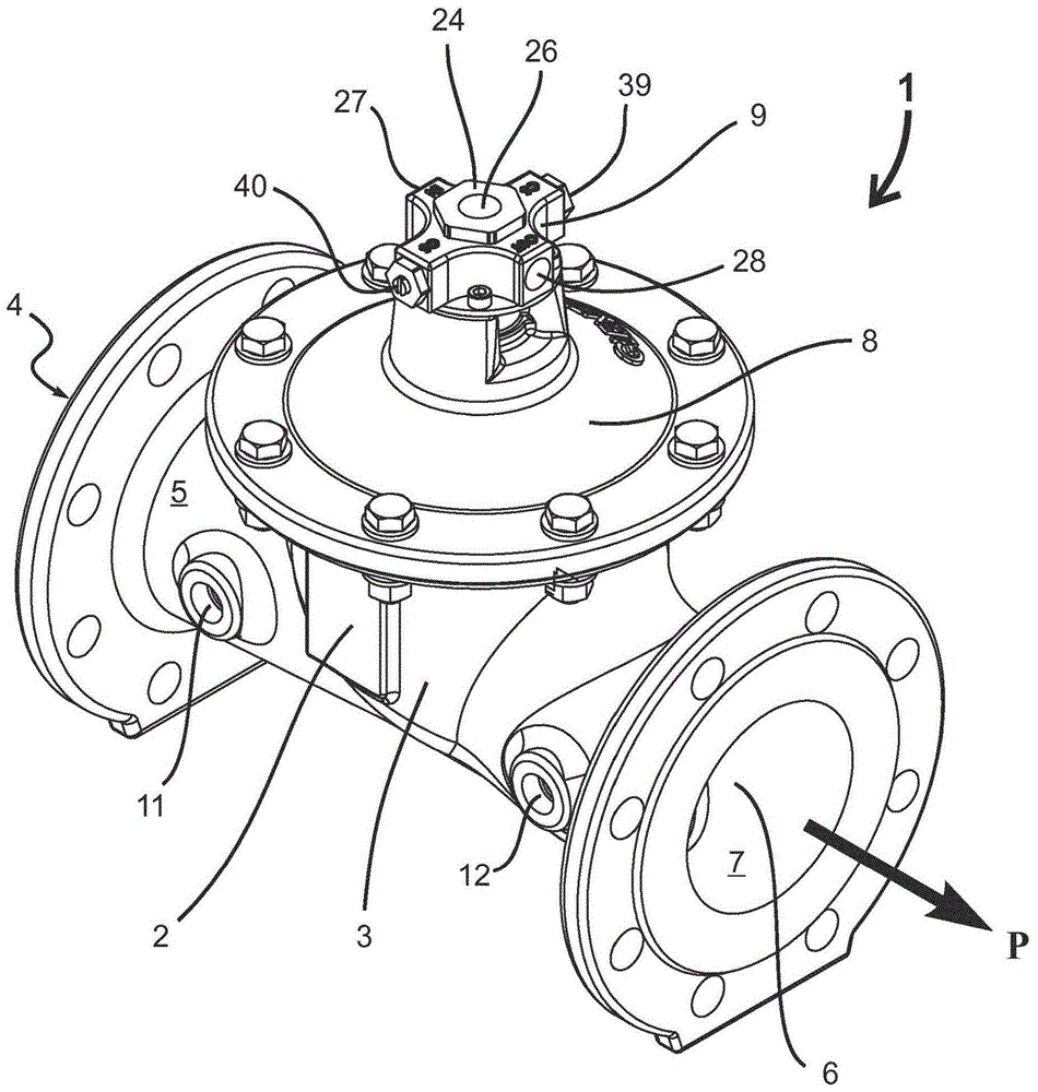
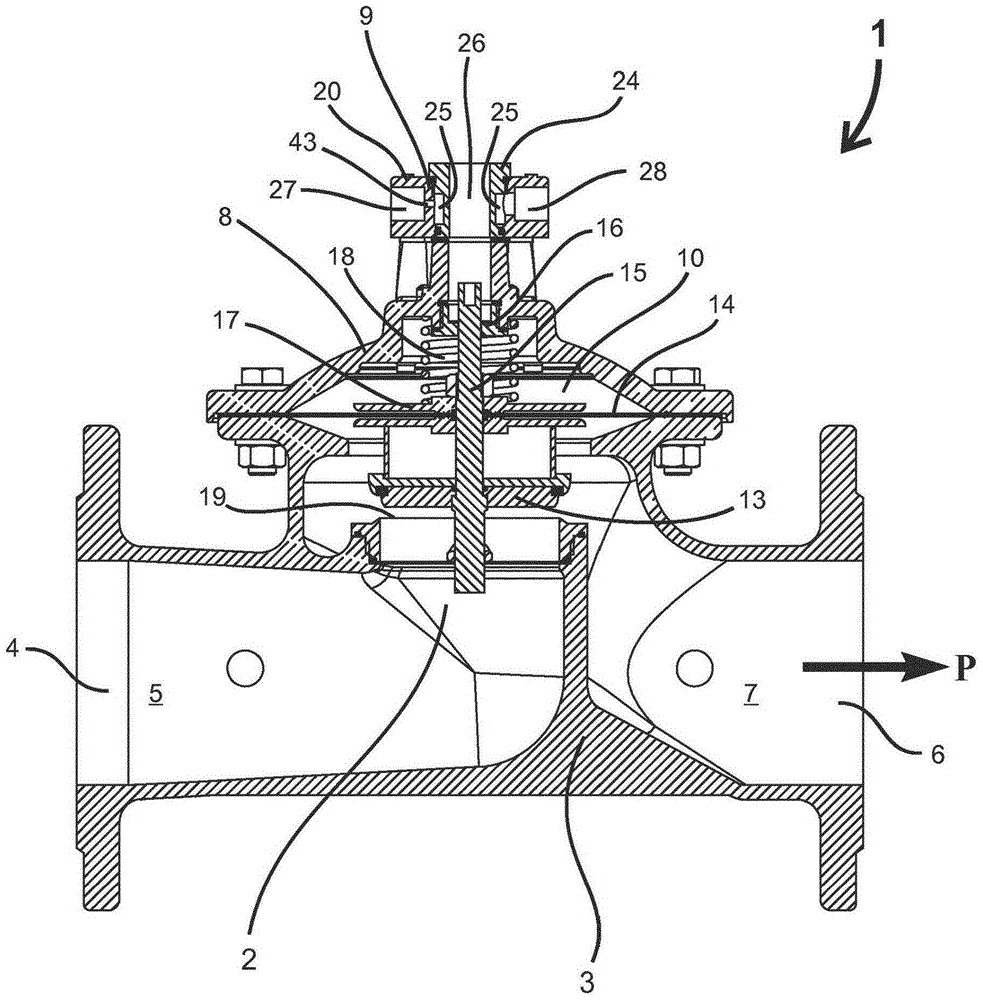
[0058] figure 1 Shown is a perspective view of a hydraulic control valve assembly 1 for use in a hydraulic control system for performing control functions in a water supply network in response to changes in water pressure fluctuations. The hydraulic control valve assembly 1 comprises a control valve 2 comprising a valve body 3 defining from an inlet 4 on the high pressure side 5 of the control valve 2 to a low pressure side 7 of the control valve 2 in the lower part of the control valve 3 Main channel on Exit 6. The general direction of the main flow M is indicated by the arrow P and coincides with the longitudinal direction of the hydraulic control valve assembly 1 . The valve body also comprises a first tap 11 for branching off the control flow C from the main flow M at the high pressure side 5 of the control valve 2, and a second tap 12. For returning the control flow C to the main flow at the low pressure side 7 of the control valve 2 . In vertical direction, the valve ...


PUM


Abstract

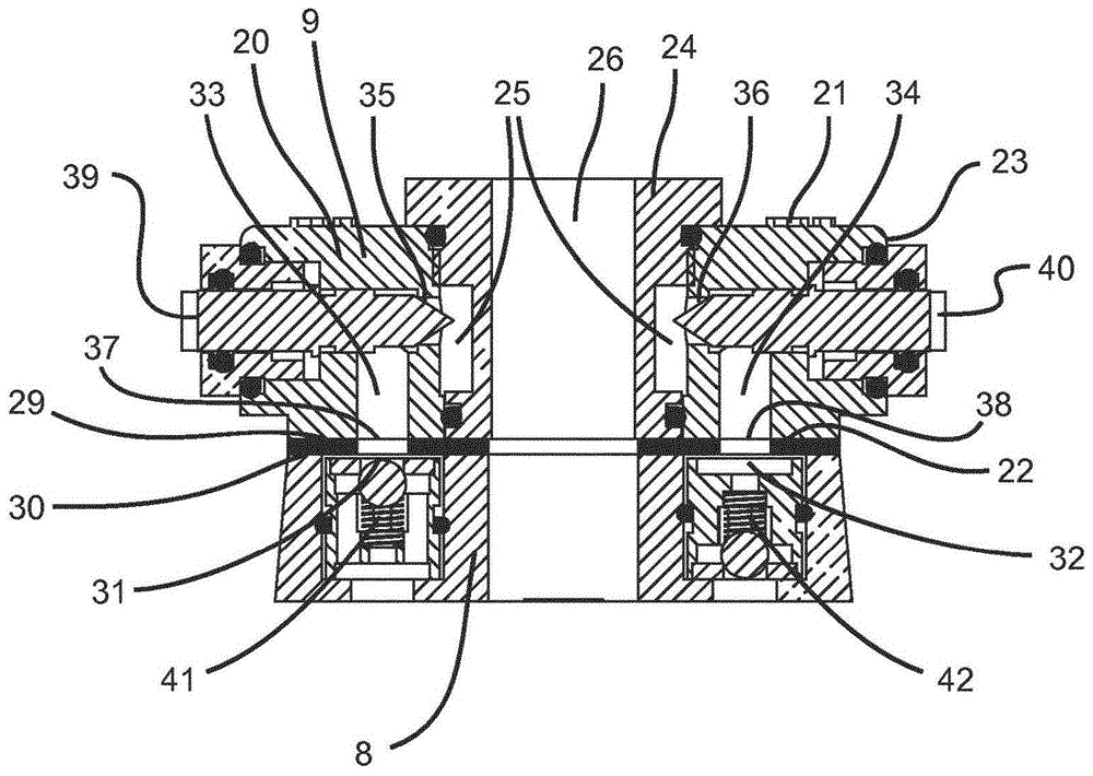
The invention discloses a modular hydraulic control valve assembly (1), which is used in a pilot-controlled hydraulic control system. The assembly includes a control valve (2), and the control valve includes: a valve body (3), defined from Main flow passage from the inlet (4) on the high pressure side (5) of the control valve to the outlet (6) on the low pressure side (7) of the control valve; the valve member (13), arranged in the main flow passage and moving the high pressure side separated from the low pressure side; a control chamber (10) comprising actuation means for hydraulically actuating the valve member by applying a control pressure to the control chamber so as to position the valve member between an open position and a closed position, thereby The main flow through the main flow channel is adjusted in response to the control pressure; the supply port (31) is used to supply fluid to the control chamber to increase the control pressure in the control chamber; the discharge port (32) is used to discharge the fluid from the control chamber chamber discharge to reduce the control pressure in the control chamber; and the valve cover (8), which closes the control chamber. The assembly also includes: a supply check valve (41) for determining the direction of supply flow; a discharge check valve (42) for determining the direction of discharge flow; a distribution block (9) comprising a common chamber in fluid communication with the common chamber A control input (27) and a control output (28) in fluid communication with the common chamber, wherein the distribution block also includes a supply channel (31) and a discharge channel (32), the supply channel is connected to the common by an adjustable supply restriction The chamber is connected to the supply port, and the discharge channel connects the common chamber to the discharge port through an adjustable discharge restriction.

Description

technical field [0001] The present invention relates to the technical field of water supply networks, and more particularly to the field of pilot operated (pilot operated) hydraulic control systems for use in water supply networks. [0002] According to a particular aspect, the present invention relates to a modular hydraulic control valve assembly for use in a pilot-operated hydraulic control system, the assembly comprising a control valve comprising: Main flow passage from the inlet on the high pressure side of the valve to the outlet on the low pressure side of the control valve; the valve member, which is arranged in the main flow passage and isolates the high pressure side from the low pressure side; the control chamber, the control chamber Including actuating means for hydraulic actuation of the valve member, the actuating device regulates the flow through the The flow rate of the main channel; the supply port, which is used to supply fluid to the control chamber to inc...

Claims


Application Information

Patent Timeline
IPC IPC(8): F16K31/36G05D16/16
CPCF16K27/02F16K31/385G05D16/163Y10T137/7759Y10T137/7768F15B13/0426F16K31/36
Inventor 克里斯蒂安·亨里克·西蒙森
Owner AVK HLDG AS
Learn More