
Fish feeding device

A component and silo technology, which is applied in the field of floating automatic detection, throwing and feeding devices, can solve the problems of increasing labor intensity, affecting economic benefits, restricting flexibility, etc. Effect

Inactive Publication Date: 2015-02-18
山东师范大学附属中学
View PDF6 Cites 13 Cited by
  • Summary
  • Abstract
  • Description
  • Claims
  • Application Information

AI Technical Summary

Problems solved by technology

[0002] The existing throwing fish feeding device, in order to control the cost, mostly uses a motor with a fixed speed, but due to the fixed speed, it is difficult to obtain different throwing distances, which greatly reduces the coverage of the feed, causing the fish to eat the bait. hoarding
At the same time, there is no automatic device, most of them are fed manually, and the amount of fish feed that is thrown and fed depends on experience, and there is no reference to accurate values, which wastes manpower and the degree of automation is very low.
On the other hand, the throwing range of the throwing fish feeding device is limited and cannot achieve 360-degree throwing without dead angles. The weak fish cannot eat enough bait, which eventually leads to inconsistent growth and size of individuals
When selling, it must be manually selected, which increases labor intensity, prolongs working hours, and lowers the price, which affects economic benefits. At the same time, fish feeders are mostly fixed on the shore or in the center of the pond. In order to obtain a more ideal throwing distance, the structural size will inevitably be increased. Therefore, this This larger size restricts its flexibility, making it unable to float directly on the water surface, making it difficult to apply to fish feeding in rivers and seas

Method used


Image

  • Fish feeding device
  • Fish feeding device
  • Fish feeding device

Examples


Embodiment Construction

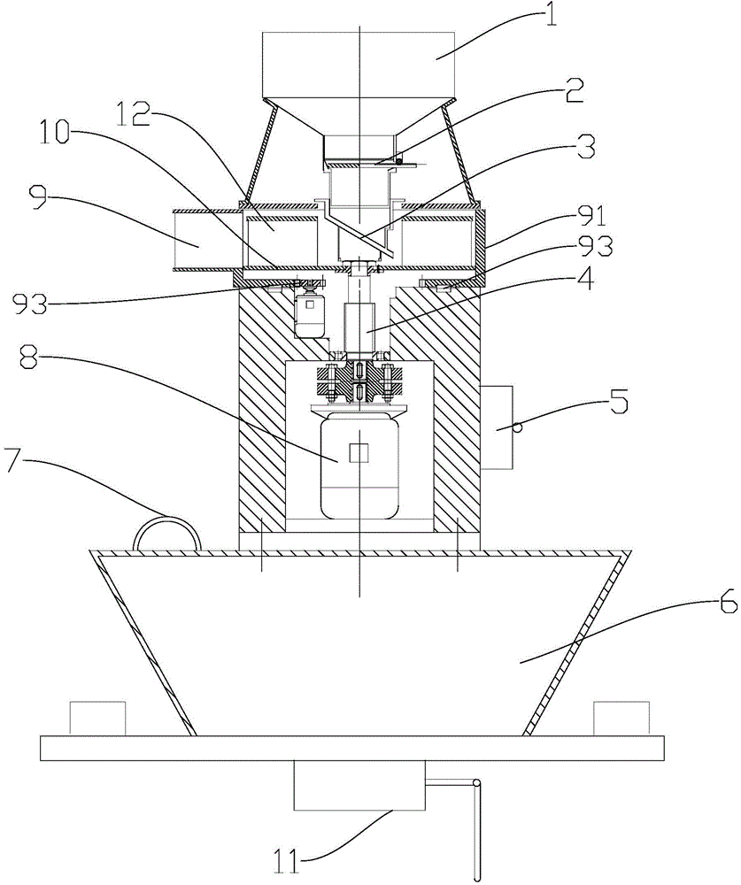
[0018] The specific implementation manners of the present invention will be described below in conjunction with the accompanying drawings. Such as Figure 1-4 As shown, the fish feeding device includes a feed bin 1, an automatic control valve 2, a directional plate 3, an input shaft 4, a controller 5, a floating cup 6, a fixed ring 7, a motor 8, a rotating outlet 9, an impeller disc 10, Fish detection sonar11.

[0019] According to the structure, it is divided into three parts: upper, middle and lower parts, which are: fish food inlet part; throwing part; power input part; fish detection sonar; floating cup; controller.

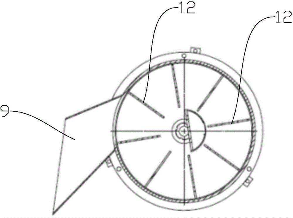
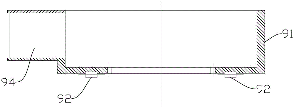
[0020] The throwing parts include a cylinder body, an impeller disc 10, a directional disc 3, and a rotating outlet 9. The cylinder body is a cylindrical structure, and the inside of the cylinder body is an impeller disc 10. The impeller disc 10 is a disc-shaped structure, and the upper surface of the disc-shaped structure There is a vertical impeller blade...


PUM


Abstract

The invention relates to a fish feeding device. The fish feeding device comprises a support body, a feed bin, a throwing component and a power input component, wherein the throwing component is communicated with the feed bin, and the power input component is used for driving a rotary feed outlet of the throwing component to rotate; a directional disc is mounted in the rotary feed outlet. The fish feeding device is characterized by further comprising a floating cup which is mounted at the bottom of the support body, wherein a bracket is further mounted at the bottom of the floating cup, a fish detecting sonar which is used for detecting fish stocks is mounted on the bottom face of the bracket and transmits obtained detection signals into a controller, and the controller feeds back output signals to a motor of the power input component. According to the device, a structural basis is provided for flexible feeding.

Description

technical field [0001] The invention relates to a fish feeding device, in particular to a floating automatic detection throwing fish feeding device. Background technique [0002] The existing throwing fish feeding device, in order to control the cost, mostly uses a motor with a fixed speed, but due to the fixed speed, it is difficult to obtain different throwing distances, which greatly reduces the coverage of the feed, causing the fish to eat the bait. The phenomenon of hoarding and grabbing food. At the same time, there is no automatic device, and most of them are fed manually, and the amount of fish feed that is thrown and fed depends on experience, and there is no reference to accurate values, which wastes manpower and has a low degree of automation. On the other hand, the throwing range of the fish throwing and feeding device is limited and cannot reach 360 omnidirectional throwing without dead angles, and weak fish cannot eat enough bait, which eventually leads to inc...

Claims


Application Information

Patent Timeline
IPC IPC(8): A01K61/02
CPCA01K61/80
Inventor 张锐杰王俊亮
Owner 山东师范大学附属中学
Learn More