Underground continuous wall reinforcing mesh interweaving machine

A technology of underground diaphragm wall and steel mesh, which is applied in the field of automatic steel bar weaving mechanism and underground diaphragm wall steel mesh interweaving machine, which can solve the problems of manpower consumption, large size of steel cage, unsafety, etc., so as to improve efficiency and reduce the amount of human labor Effect

Active Publication Date: 2015-02-18
GEOTECHN TECH
View PDF4 Cites 7 Cited by
  • Summary
  • Abstract
  • Description
  • Claims
  • Application Information

AI Technical Summary

Problems solved by technology

At present, on construction sites, drilling machines are generally used to form pile holes in the foundation soil. Workers weave steel cages, put the steel cages into the pile holes, and then pour concrete building foundations into them. There are complicated steps, low efficiency, and manpower consumption. In addition, the established foundation wall is not continuous, and its strength is low; the existing underground continuous wall is generally firstly excavated with a variety of grooving machines to guide wall grooves in the ground, and then put the guide wall formwork in the grooves for support , and then manually weld the steel cage, use a crane to vertically put the steel cage into the guide wall groove, and finally pour concrete into it, the steps are complicated and the efficiency is low, and the steel cage is large in size, so it is difficult to lift and put it into the guide wall groove ; The existing operation method needs to manually climb into the soil tank below the ground to work, which is unsafe

Method used


Image

  • Underground continuous wall reinforcing mesh interweaving machine
  • Underground continuous wall reinforcing mesh interweaving machine
  • Underground continuous wall reinforcing mesh interweaving machine

Examples


Embodiment Construction

[0028] The present invention will be further described below in conjunction with the accompanying drawings and embodiments.

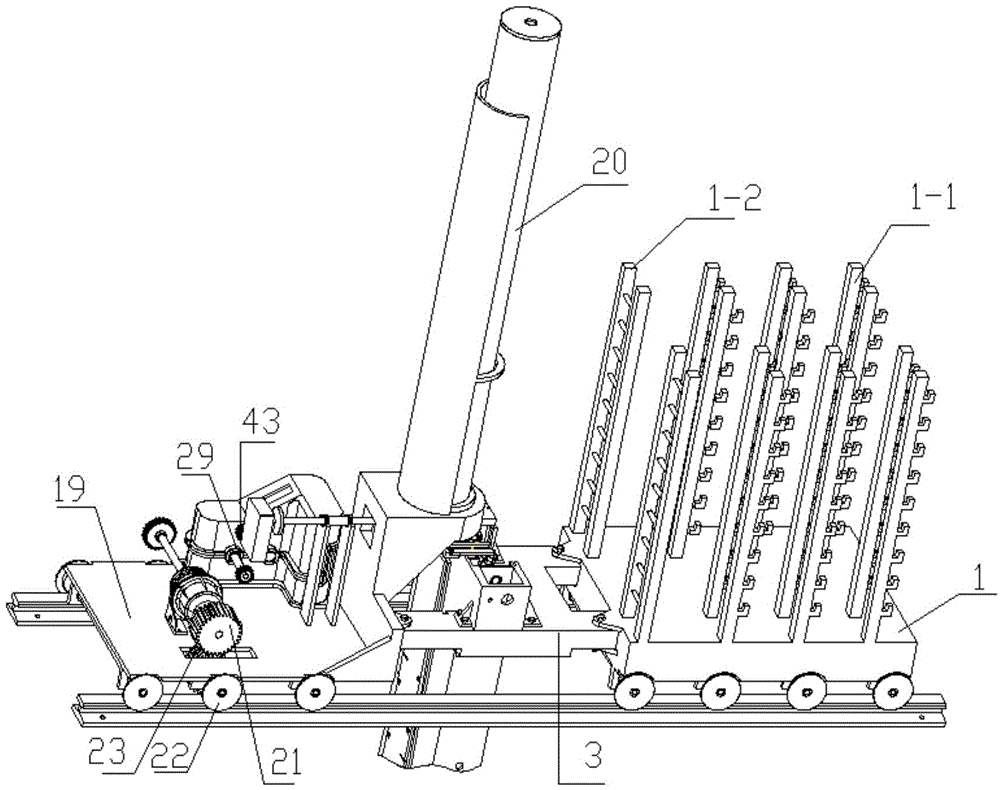
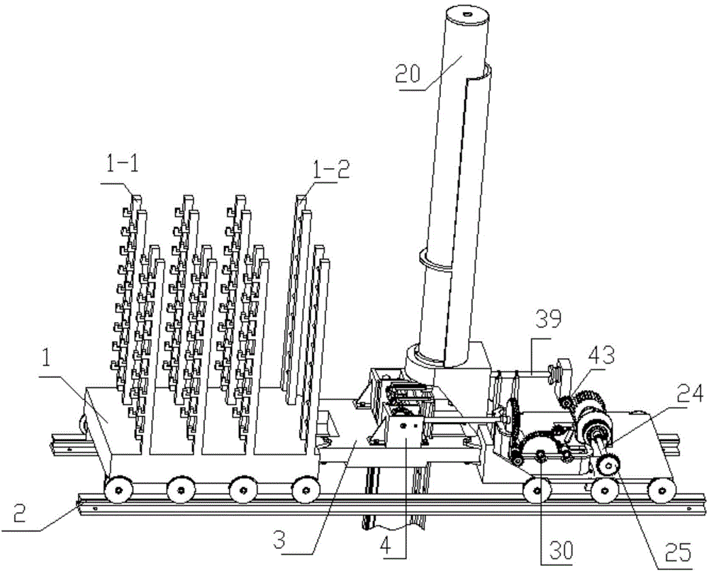
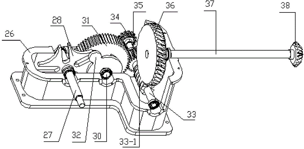
[0029] Such as figure 1 , 2, 3 and 5, a steel mesh interweaving machine for underground diaphragm walls, comprising a driving compartment 19, a driven compartment 1, an intermediate support frame 3, a drive mechanism, an intermittent transmission mechanism, a transverse reinforcement rope storage rack, and a transverse reinforcement rope interweaving mechanism and the longitudinal reinforcement conveying mechanism; the active carriage 19 is fixedly provided with a longitudinal reinforcement conveying mechanism support 19-1; the bottom of the longitudinal reinforcement conveying mechanism is connected with the active carriage 19 by bolts, and the middle part is supported on the longitudinal reinforcement conveying mechanism support 19-1; intermittent transmission The bottom end of the mechanism is connected with the active carriage 19 by bolts; the two ...


PUM


Abstract

The invention discloses an underground continuous wall reinforcing mesh interweaving machine. In an existing underground continuous wall, a reinforcing steel cage is vertically placed in a guide wall slot by using a crane generally, and the reinforcing steel cage is difficult to hoist and put into the guide wall slot due to large size. According to the underground continuous wall reinforcing mesh interweaving machine, a longitudinal reinforcing steel conveying mechanism is fixed with a driving carriage; an intermittent transmission mechanism is fixed with the driving carriage; two ends of an intermediate support frame are respectively fixed with the driving carriage and a driven carriage; a transverse reinforcing steel rope interweaving mechanism is fixed with the intermediate support frame; a drive mechanism drives the driving carriage and the intermittent transmission mechanism; the intermittent transmission mechanism respectively transmits power to the transverse reinforcing steel rope interweaving mechanism and a longitudinal reinforcing steel conveying mechanism; the transverse reinforcing steel rope interweaving mechanism is used for interweaving reinforcing steel ropes, provided by a transverse reinforcing steel rope storage rack, to and fro; the longitudinal reinforcing steel conveying mechanism is used for enabling reinforcing steel to drop into the reinforcing steel ropes interwoven by the transverse reinforcing steel rope interweaving mechanism to form a reinforcing mesh. According to the underground continuous wall reinforcing mesh interweaving machine, the reinforcing mesh can be automatically woven into an underground continuous wall guide wall slot, and further an underground continuous wall can be fast built.

Description

technical field [0001] The invention belongs to the field of construction engineering and relates to an automatic steel bar weaving mechanism, in particular to an underground continuous wall steel bar mesh interweaving machine. Background technique [0002] The foundation is the foundation of a building. With the development of the construction industry, the requirements for the efficiency of laying the foundation are getting higher and higher. At present, on construction sites, drilling machines are generally used to form pile holes in the foundation soil. Workers weave steel cages, put the steel cages into the pile holes, and then pour concrete building foundations into them. There are complicated steps, low efficiency, and manpower consumption. In addition, the established foundation wall is not continuous, and its strength is low; the existing underground continuous wall is generally first excavated by various digging machines to guide wall grooves in the ground, and the...

Claims


Application Information

Patent Timeline
Patent Type & Authority Applications(China)
IPC IPC(8): B21F27/20
Inventor 潘金龙俞高红殷树芳吴国环王智群杜立恒
Owner GEOTECHN TECH
Why Eureka
Try Eureka