Planing machine body of gantry planing machine

A technology of gantry planer and bed, which is applied in the field of mechanical processing, and can solve the problems of troublesome chip removal workers, difficult follow-up strokes, and low planing efficiency.

Inactive Publication Date: 2015-02-18
CHONGQING XIHUA BELT PULLEY MACHINERY MFG CO LTD
View PDF0 Cites 2 Cited by
  • Summary
  • Abstract
  • Description
  • Claims
  • Application Information

AI Technical Summary

Problems solved by technology

After each trip, it must be cleaned in time, otherwise it is easy to damage the equipment, and it will be difficult to carry out subsequent trips
The existing swarf removal is all done manually, because the opening of the through groove is small, it will inevitably bring some troubles to the swarf removal workers, and the swarf removal efficiency is low, resulting in low overall planing efficiency

Method used


Image

  • Planing machine body of gantry planing machine
  • Planing machine body of gantry planing machine
  • Planing machine body of gantry planing machine

Examples


Embodiment Construction

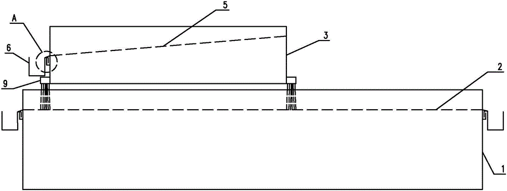
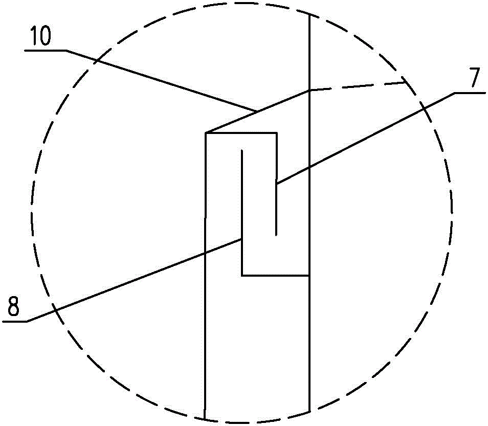
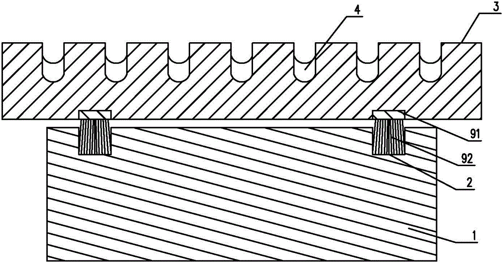
[0015] Below in conjunction with accompanying drawing and specific embodiment the present invention will be described in further detail:

[0016] Such as figure 1 , figure 2 with image 3 As shown, a bed of a gantry planer includes a base 1, on which a horizontal guide rail 2 is provided, on which a workbench 3 reciprocating along the guide rail 2 is provided; The horizontal through groove 4, the bottom of the through groove 4 is a slope 5; the cross section of the bottom of the through groove 4 is arc-shaped; one end of the workbench 3 is provided with a chip receiving groove 6, and the notch of the chip receiving groove 6 is located at At the bottom of the inclined surface 5, a gripping part 7 is provided on the chip receiving groove 6, and a hook part 8 matching the gripping part 7 is provided on the worktable 3; a guide plate 10 is also provided at the gripping part 7, when the gripping part 7 and After the hook portion 8 is connected, the guide plate 10 is just flush ...


PUM


Abstract

The invention relates to a planing machine body of a gantry planing machine. The planing machine body comprises a base, wherein horizontal guide rails are arranged on the planing machine body, a worktable is arranged on the guide rails and does reciprocating movement along the guide rails, horizontal through grooves are formed in the worktable and are used for fixing a workpiece, the bottom part of each through groove is provided with an inclined surface, and a chip receiving groove is formed in one end of the worktable, is positioned at the bottom end of each inclined surface, and is detachably connected with the worktable. The planing machine body has the beneficial effects that the worktable can do reciprocating movement, the certain vibration will be generated, and planing chips in each through groove will fall onto the bottom end of the corresponding inclined surface, and then fall into the corresponding chip receiving groove; the planing chips in the through grooves are automatically discharged into the chip receiving grooves.

Description

technical field [0001] The invention relates to the field of mechanical processing, in particular to a bed of a planer. Background technique [0002] The gantry planer is mainly used for planing large workpieces, and can also clamp multiple parts on the workbench to process at the same time. It is the mother machine of industry. It is mainly composed of bed, beam, top beam, column, vertical tool holder, side tool holder, feed box and other parts; the bed includes a base and a worktable on the base. The base is provided with horizontal guide rails, and the workbench is provided with horizontal through grooves for fixing workpieces. During processing, the worktable on the horizontal guide rail of the base carries the workpiece through the portal frame for linear reciprocating motion. [0003] Existing planer can produce a lot of shavings when processing workpiece, and these shavings can fall in the horizontal channel of workbench. After each trip, it must be cleaned up in t...

Claims


Application Information

Patent Timeline
Patent Type & Authority Applications(China)
IPC IPC(8): B23Q1/01B08B1/00
CPCB23Q1/015B23Q11/0042
Inventor 唐建瑶
Owner CHONGQING XIHUA BELT PULLEY MACHINERY MFG CO LTD
Why Eureka
Try Eureka