Unlock instant, AI-driven research and patent intelligence for your innovation.

Clamping-position-adjustable pipe clamping device

An adjustable, clamping device technology, applied in positioning device, clamping, supporting and other directions, can solve the problems of poor clamping firmness, poor adjustability, large opening and closing degree, etc., and achieves convenient operation, simple structure and low production cost. Effect

Active Publication Date: 2015-02-18
安徽鼎恒再制造产业技术研究院有限公司
View PDF13 Cites 37 Cited by
  • Summary
  • Abstract
  • Description
  • Claims
  • Application Information

AI Technical Summary

Problems solved by technology

[0002] At present, the use of pipe fittings is very common, so the processing of pipe fittings is also becoming more and more popular, such as cutting, grinding, welding, etc. Since most of the pipe fittings are cylindrical structures, the clamping work of pipe fittings during processing has a great impact on the processing quality of pipe fittings. It plays a decisive role; the current pipe clamping equipment generally has the characteristics of single structure and poor adjustability.
[0003] The Chinese patent No. 201410183586.X discloses a pipe clamping device, which can realize the detachable function, and expand the scope of application of the pipe clamping device by changing the clamping size of the clamping device; the patent The Chinese patent No. 201110460268.X discloses a clamping mechanism for pipe fittings, which can automatically take out the copper pipes bent by the CNC pipe bending machine. Automatic production of pipe machines; the Chinese patent No. 200920286575.9 discloses a pipe clamping device, which improves the safety performance of clamping to a certain extent; In terms of adjustment, the clamping firmness is poor

Method used


Image

  • Clamping-position-adjustable pipe clamping device
  • Clamping-position-adjustable pipe clamping device

Examples


Embodiment Construction

[0014] In order to make the technical means, creative features, goals and effects achieved by the present invention easy to understand, the present invention will be further described below in conjunction with specific illustrations.

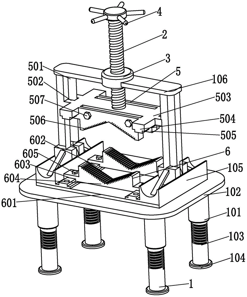
[0015] Such as figure 1 As shown, a clamping device with adjustable clamping position according to the present invention includes a lifting bracket platform 1, a screw 2, a nut 3, a hand wheel 4, a clamping device 5 and a fixing device 6, and the screw 2 is located above the lifting bracket platform 1, and the screw 2 is installed on the lifting bracket platform 1 through the nut 3; the handwheel 4 is fixed on the top of the screw 2, and the clamping device 5 is installed on the bottom of the screw The hand wheel 4 drives the rotation of the lead screw 2, thereby driving the lead screw 2 to move up and down in the nut 3, and then drives the clamping device 5 to move up and down on the vertical plane, thereby achieving the clamping effect on the ...


PUM


Abstract

The invention relates to a clamping-position-adjustable pipe clamping device, comprising a lifting supporting platform, a screw rod, a nut, a hand wheel, a clamping device and a fixing device, wherein the screw rod is located above the lifting supporting platform; moreover, the screw rod is installed on the lifting supporting platform through the nut; the hand wheel is fixedly arranged on the top end of the screw rod; the clamping device is installed on the bottom end of the screw rod; the screw rod is driven to rotate by rotating the hand wheel, so that the screw rod is driven to move up and down in the nut, and then the clamping device is driven to move up and down on a vertical plane; an effect of clamping a pipe fitting is realized; the fixing device is located right below the clamping device; moreover, the fixing device is fixedly connected with the lifting supporting platform. The device has the advantages of simple structure, convenience in operation, low manufacturing cost and the like; by applying the device, a function of axially adjusting a clamping position can be realized; moreover, as the device is adjustable in height and angle, pipe fitting cutting, grinding, welding and other work can be implemented more conveniently.

Description

technical field [0001] The invention relates to the field of clamping tools for pipe fittings, in particular to a clamping device with adjustable clamping positions. Background technique [0002] At present, the use of pipe fittings is very common, so the processing of pipe fittings is also becoming more and more popular, such as cutting, grinding, welding, etc. Since most of the pipe fittings are cylindrical structures, the clamping work of pipe fittings during processing has a great impact on the processing quality of pipe fittings. It plays a decisive role; the current pipe clamping equipment generally has the characteristics of single structure and poor adjustability. [0003] The Chinese patent No. 201410183586.X discloses a pipe clamping device, which can realize the detachable function, and expand the scope of application of the pipe clamping device by changing the clamping size of the clamping device; the patent The Chinese patent No. 201110460268.X discloses a clam...

Claims


Application Information

Patent Timeline
IPC IPC(8): B23Q3/08
CPCB23Q3/064
Inventor 程敬卿薛卫昌
Owner 安徽鼎恒再制造产业技术研究院有限公司
Features
  • R&D
  • Intellectual Property
  • Life Sciences
  • Materials
  • Tech Scout
  • Unparalleled Data Quality
  • Higher Quality Content
  • 60% Fewer Hallucinations
Learn More