Non-axial force biserial radial piston pump distributing oil on end surface

A technology with no axial force and radial columns, which is applied in the direction of parts, pumps, multi-cylinder pumps, etc. of pumping devices for elastic fluids, and can solve the problem of poor working of pumps for a long time, easy vibration and bending, and spring elements Difficult design and other problems, to achieve the effect of compact structure, less processing amount, and small axial dimension

Inactive Publication Date: 2015-02-18
XI AN JIAOTONG UNIV
View PDF7 Cites 9 Cited by
  • Summary
  • Abstract
  • Description
  • Claims
  • Application Information

AI Technical Summary

Problems solved by technology

[0003] At present, the flow distribution methods of radial piston pumps mainly include axial flow distribution and check valve flow distribution. Closed, the oil needs to overcome the spring to do work during the flow distribution process, and part of the energy will be lost, and the spring element on the check valve is difficult to design, and it is prone to noise and fatigue damage
For shaft distribution pumps, it is necessary to process multiple axial holes and radial grooves on the distribution shaft, which increases the complexity of shaft processing and reduces the strength of the shaft, and

Method used


Image

  • Non-axial force biserial radial piston pump distributing oil on end surface
  • Non-axial force biserial radial piston pump distributing oil on end surface
  • Non-axial force biserial radial piston pump distributing oil on end surface

Examples


Embodiment Construction

[0028] The present invention will be described in detail below in conjunction with the accompanying drawings.

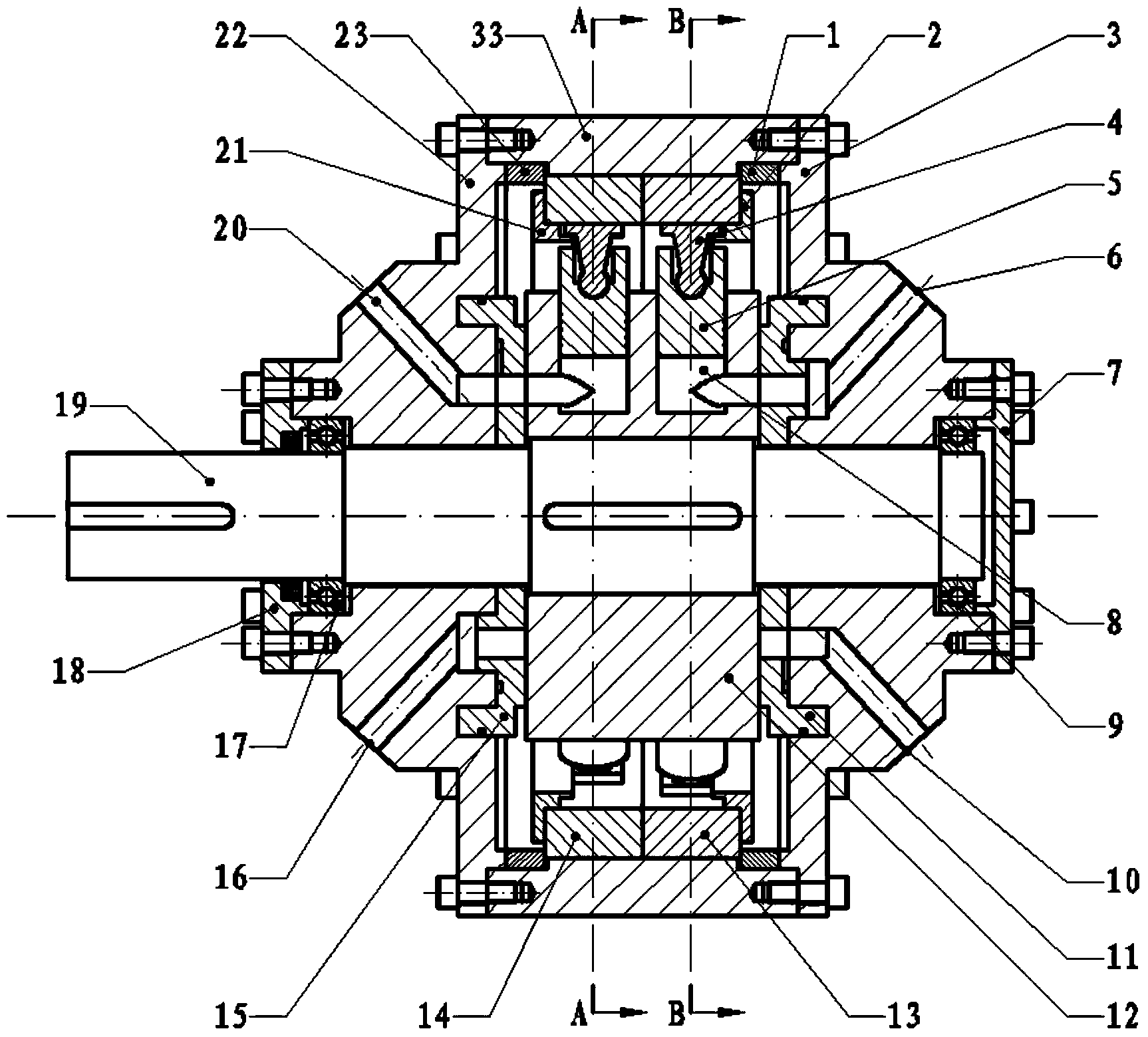
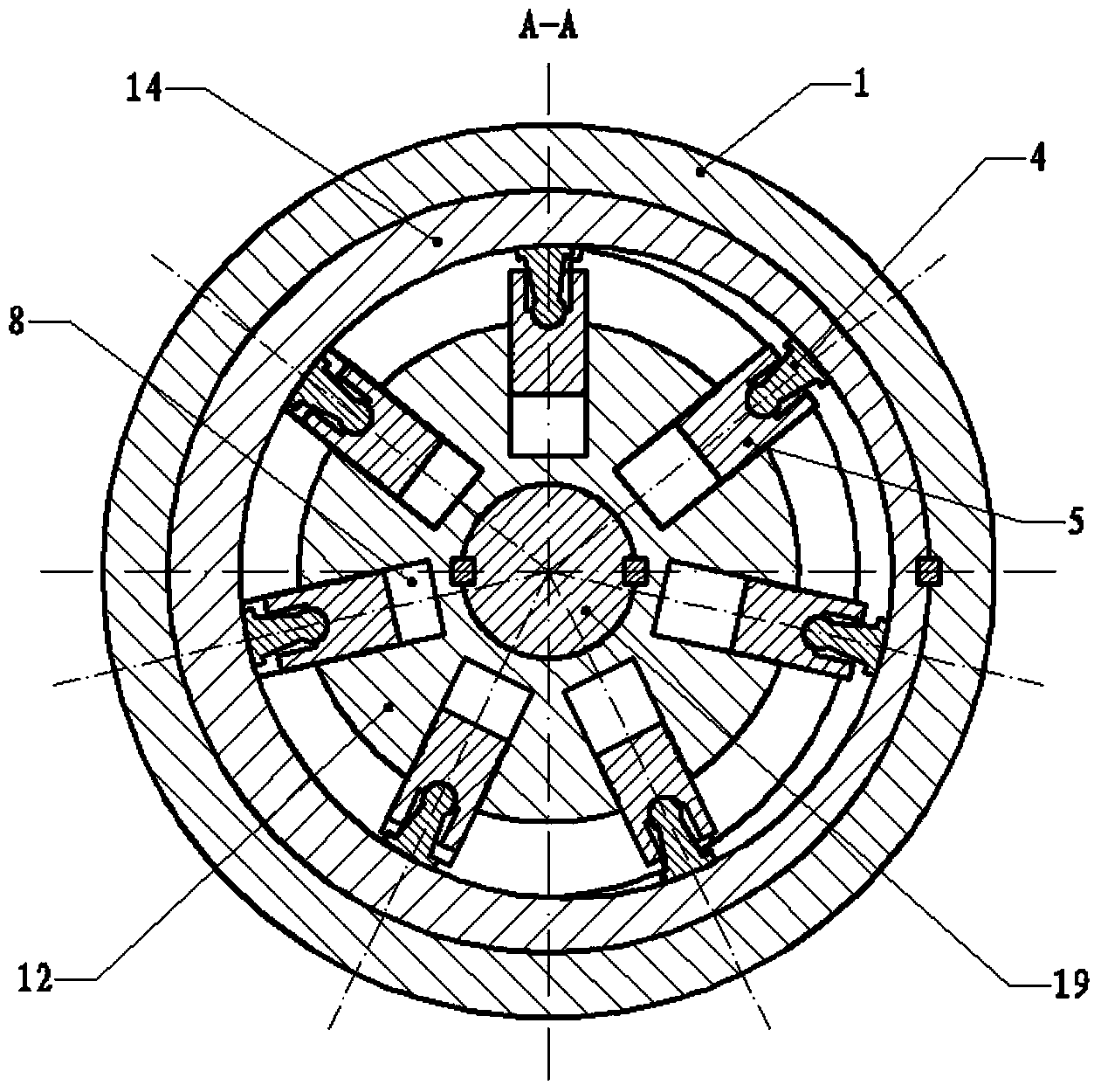
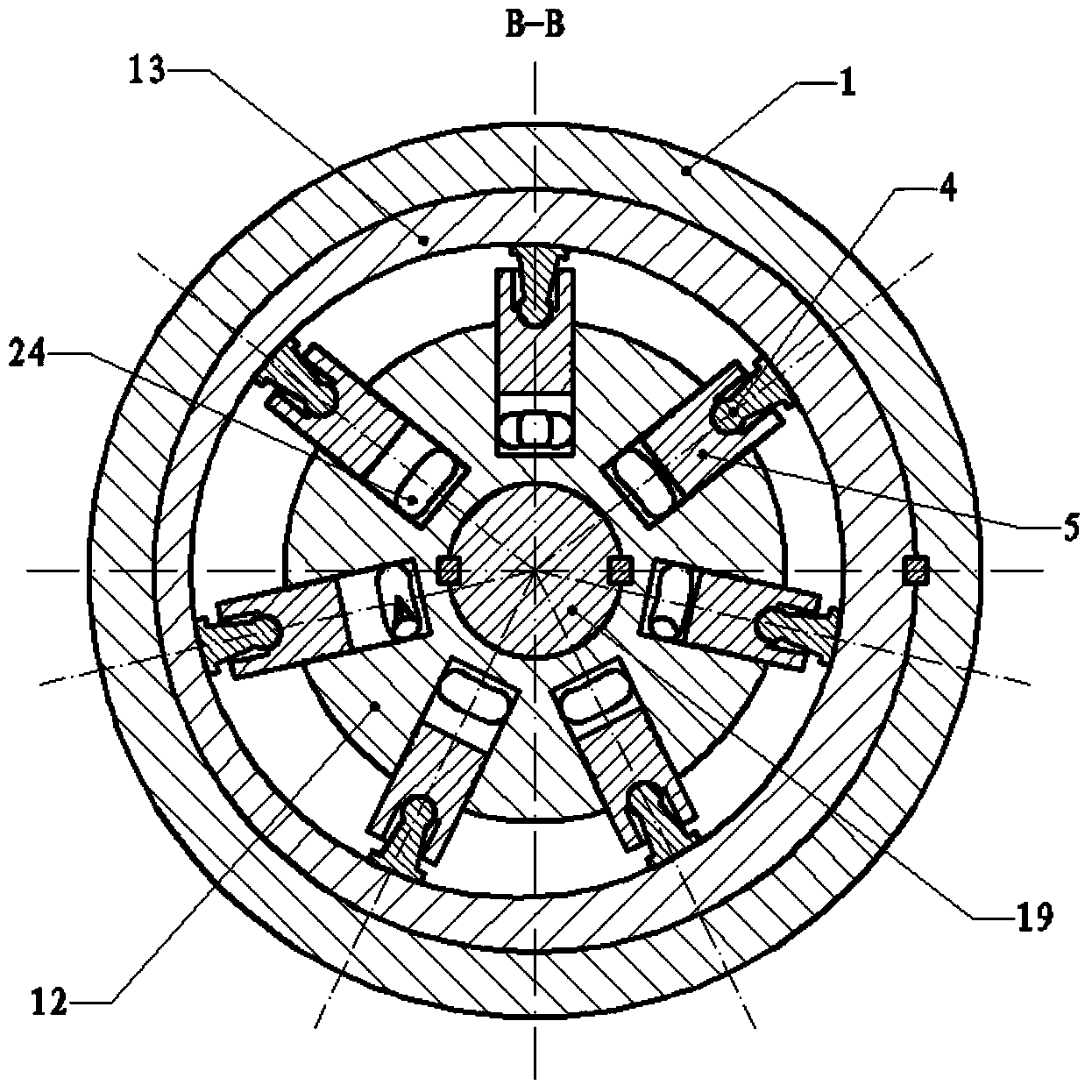
[0029] refer to figure 1 , a double-row radial piston pump with no axial force and oil distribution on the end face, including a pump housing 33, the first cam 14 and the second cam 13 are installed in the pump housing 33, and the circumferential positioning is realized by key connection, There is a certain amount of eccentricity between their inner holes and the outer cylindrical wall surface. The eccentric directions of the first cam 14 and the second cam 13 differ by 180°. The cylinder 23 and the second positioning sleeve 1 are compressed to achieve axial positioning. The first pump end cover 22 and the second pump end cover 3 have the same structure, and are respectively installed on both sides of the pump housing 33 with a difference of 180° in installation orientation. Their inner notches are respectively pressed on the first positioning sleeve 23 and the seco...


PUM


Abstract

The invention discloses a non-axial force biserial radial piston pump distributing oil on an end surface. The biserial radial piston pump comprises a pump housing body; a first cam and a second cam are mounted in the pump housing body; the angle formed between the eccentric directions of the first cam and the second cam is 180 degrees; the two ends of a transmission shaft are supported by pump end covers; a rotor is mounted on the transmission shaft; the two sides of the rotor are propped against a first flow distributing plate and a second flow distributing plate respectively; two rows of radial piston holes are formed in the outer cylinder wall of the rotor in parallel; a piston is mounted in each piston hole; connecting rod skid shoes are mounted on the pistons, and are connected through spherical hinges; the first flow distributing plate and the second flow distributing plate are mounted on the pump end covers respectively; the angle formed between the mounting directions of the first flow distributing plate and the second flow distributing plate is 180 degrees; oil absorption arc grooves and oil pressing arc grooves which are isolated mutually are formed in the first flow distributing plate and the second flow distributing plate; oil inlet holes and oil outlet holes in the pump end covers are communicated with the oil absorption arc grooves and the oil pressing arc grooves respectively. According to the invention, distribution is realized through the first flow distributing plate and the second flow distributing plate; the piston pump has the advantages that the piston pump is compact in structure, simple in transmission, low in flow fluctuation, free from axial force, and reliable in support, conducts automatic hydraulic compensation, and is stable in operation, and long in service life.

Description

technical field [0001] The invention belongs to the technical field of radial plunger pumps, and in particular relates to a double-row radial plunger pump with no axial force and end face oil distribution. Background technique [0002] The main pump in the hydraulic system in forging, metallurgy, shipbuilding and other fields generally adopts a radial piston pump with high output pressure, large displacement and high volumetric efficiency. [0003] At present, the flow distribution methods of radial piston pumps mainly include axial flow distribution and check valve flow distribution. Closed, the oil needs to overcome the spring to do work during the flow distribution process, which will lose part of the energy, and the spring element on the check valve is difficult to design, and it is prone to noise and fatigue damage. For shaft distribution pumps, it is necessary to process multiple axial holes and radial grooves on the distribution shaft, which increases the complexity ...

Claims


Application Information

Patent Timeline
IPC IPC(8): F04B1/113F04B53/16F04B53/14F04B53/00
Inventor 赵升吨郭桐李靖祥韩晓兰刘辰张晨阳
Owner XI AN JIAOTONG UNIV
Why Eureka
Try Eureka