Quick detecting device and method for defective equipment of transformer substation

A detection device and substation technology, applied in measurement devices, radio wave measurement systems, testing dielectric strength, etc., can solve the problems that monitoring devices consume a lot of time and manpower, discharge faults, difficult to adapt to remote management of smart substations, and few people on duty. requirements, etc.

Inactive Publication Date: 2015-02-18
STATE GRID CORP OF CHINA +1
View PDF6 Cites 11 Cited by
  • Summary
  • Abstract
  • Description
  • Claims
  • Application Information

AI Technical Summary

Problems solved by technology

[0005] 1) Any high-voltage power equipment in the substation may have a discharge fault. If you want to monitor the primary electrical equipment in the whole station, you need to install a discharge monitoring device on each equipment, which requires a lot of time and financial resources. Equipment procurement and installation;
[0006] 2) It is necessary to carry multiple sets of different types of instruments during the test, which is inconvenient to operate;
[0007] 3) The maintenance and management of numerous monitoring devices takes a lot of time and manpower
[0008] Therefore, the current form of monitoring is difficult to meet the requirements of remote management of smart substations and fewer people on duty in the future

Method used


Image

  • Quick detecting device and method for defective equipment of transformer substation
  • Quick detecting device and method for defective equipment of transformer substation
  • Quick detecting device and method for defective equipment of transformer substation

Examples


Embodiment Construction

[0099] The specific implementation manners according to the present invention will be described below in conjunction with the accompanying drawings.

[0100] In the following description, many specific details are set forth in order to fully understand the present invention, but the present invention can also be implemented in other ways different from those described here, therefore, the present invention is not limited to the specific embodiments disclosed below limit.

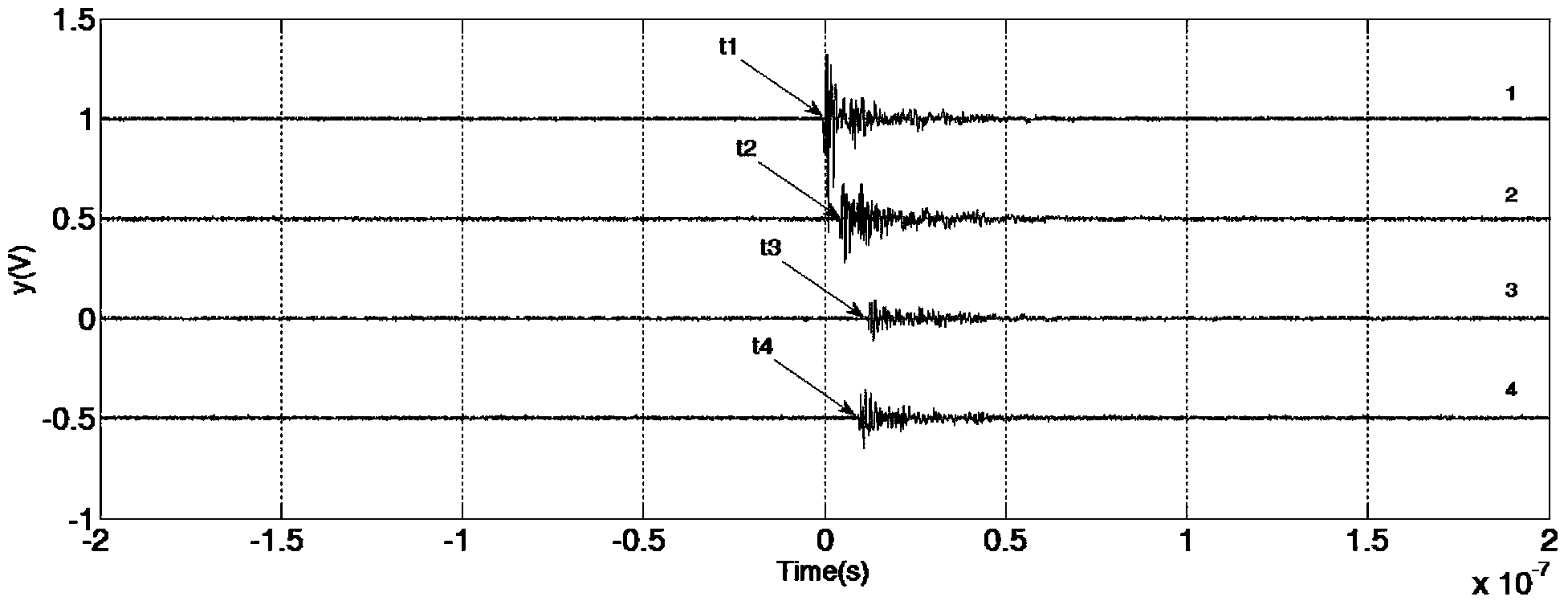
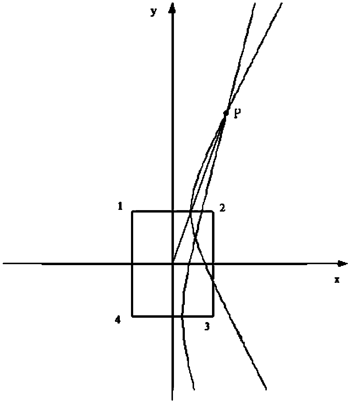
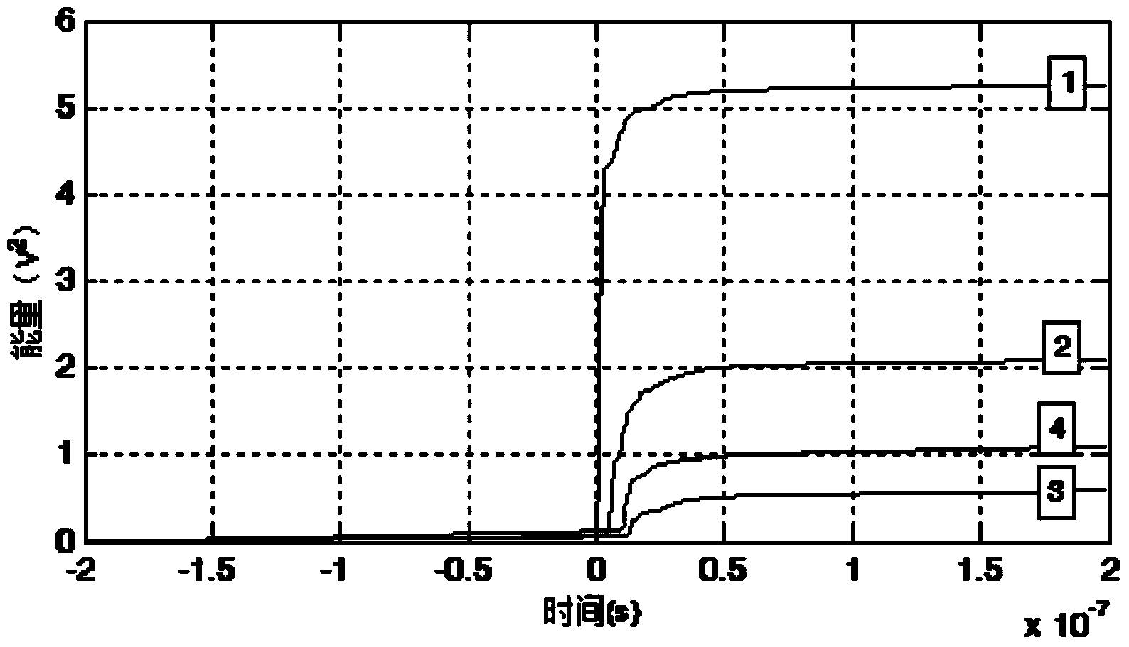
[0101] The device of the present invention starts to work after moving to the substation site and fixing it at a certain position. According to the partial discharge electromagnetic wave signal information received by the four UHF omnidirectional sensors, it can control all kinds of power transmission and transformation primary equipment in the substation, including GIS outlet bushings, The discharge signal generated before the insulation fault of transformer high-voltage bushing, SF6 circuit breaker, transf...


PUM

PropertyMeasurementUnit
Bandwidthaaaaaaaaaa

Abstract

The invention discloses a quick detecting device and method for defective electrical equipment of a transformer substation. The quick detecting device is composed of a plurality of electric wave sensors, an ultra high-speed data sampling unit and a data processing unit. The quick detecting method includes that the electric wave sensors receive electric signals generated from insulating defective discharging of the defective electrical equipment of the transformer substation to be detected; after amplified and filtered by front wide-and amplifiers, the electric signals are synchronously collected by the ultra high-speed data sampling unit and then sent to the data processing unit for data processing to four-way signals; the position of a discharging source and warning information are displayed on a display screen. By the use of the quick detecting device and method, detection and planar location of the discharging source of detective equipment in the transformer substation are facilitated, so that cost for discharge detection of the defective equipment of the transformer substation is lowered, defects are found in advance when the transformer substation equipment is under detection, power failures rarely occur, and intelligent degree of the transformer substation is improved. The quick detecting device and method has the advantages that the discharge detection of the whole transformer substation to be detected is achieved in the quick-positioning, low-cost and high-efficiency manner.

Description

technical field [0001] The invention relates to a high voltage and insulation technology of a power system, in particular to a fast detection device and a detection method for defective power equipment in a substation. Background technique [0002] Insulation fault is one of the most important possible faults in the operation of power equipment. Before the insulation fault of power equipment occurs, there will generally be a gradual discharge process, which will eventually lead to insulation breakdown. If the discharge monitoring and diagnosis of the operating equipment can be carried out during this process, the discharge signal can be found in time, and the defect can be dealt with in advance, so that the occurrence of insulation breakdown fault can be effectively avoided. The location of the discharge location is also helpful to formulate a more targeted maintenance treatment plan, reduce power outage time, and improve maintenance efficiency. [0003] Defect discharge ca...

Claims


Application Information

Patent Timeline
IPC IPC(8): G01R31/12G01S5/06
Inventor 殷军郭浩刘玄
Owner STATE GRID CORP OF CHINA
Why Eureka
Try Eureka