Array substrate and manufacturing method thereof and display device

A technology of an array substrate and a manufacturing method, applied in the field of display, can solve the problems of loss of transmittance of display panel, large step difference of color filter substrate, increase of backlight cost, etc., so as to shorten the production time, reduce the step difference, and reduce the number of patterning processes. Effect

Inactive Publication Date: 2015-02-18
HEFEI XINSHENG OPTOELECTRONICS TECH CO LTD +1
View PDF11 Cites 2 Cited by
  • Summary
  • Abstract
  • Description
  • Claims
  • Application Information

AI Technical Summary

Problems solved by technology

[0004] When the array substrate and the color filter substrate are aligned into a box, due to the limitation of the alignment accuracy, defects such as light leakage caused by alignment deviation are prone to occur.
In order to avoid light leakage, the black matrix (Black Matrix, BM) on the color filter substrate must be wide enough, but this will lose the transmittance of the display panel, increase the cost of the backlight, and cause the color filter substrate to have a large step difference

Method used


Image

  • Array substrate and manufacturing method thereof and display device
  • Array substrate and manufacturing method thereof and display device
  • Array substrate and manufacturing method thereof and display device

Examples


Embodiment 1

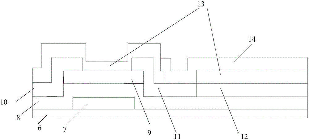
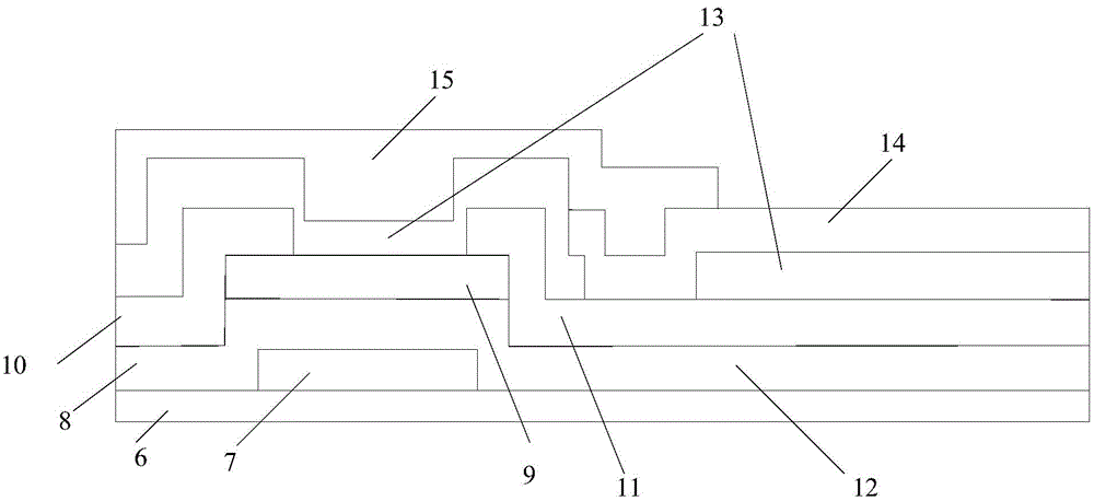
[0154] The array substrate in this embodiment is an array substrate in TN mode, and the method for manufacturing the array substrate in this embodiment specifically includes the following steps:

[0155] Step 1, providing a base substrate 6, forming patterns of gate electrodes 7 and gate lines on the base substrate 6;

[0156] Wherein, the base substrate 6 may be a glass substrate or a quartz substrate. Specifically, sputtering or thermal evaporation can be used to deposit a thickness of about The gate metal layer, the gate metal layer can be Cu, Al, Ag, Mo, Cr, Nd, Ni, Mn, Ti, Ta, W and other metals and alloys of these metals, the gate metal layer can be single-layer structure or multi-layer Structure, multi-layer structure such as Cu\Mo, Ti\Cu\Ti, Mo\Al\Mo, etc. A layer of photoresist is coated on the gate metal layer, and a mask is used to expose the photoresist, so that the photoresist forms a photoresist unreserved area and a photoresist reserved area, wherein the phot...

Embodiment 2

[0172] The array substrate in this embodiment is an array substrate in TN mode, and the method for manufacturing the array substrate in this embodiment specifically includes the following steps:

[0173] Step 1, providing a base substrate 6, forming patterns of gate electrodes 7 and gate lines on the base substrate 6;

[0174] Wherein, the base substrate 6 may be a glass substrate or a quartz substrate. Specifically, sputtering or thermal evaporation can be used to deposit a thickness of about The gate metal layer, the gate metal layer can be Cu, Al, Ag, Mo, Cr, Nd, Ni, Mn, Ti, Ta, W and other metals and alloys of these metals, the gate metal layer can be single-layer structure or multi-layer Structure, multi-layer structure such as Cu\Mo, Ti\Cu\Ti, Mo\Al\Mo, etc. A layer of photoresist is coated on the gate metal layer, and a mask is used to expose the photoresist, so that the photoresist forms a photoresist unreserved area and a photoresist reserved area, wherein the phot...

Embodiment 3

[0188] The array substrate in this embodiment is an array substrate in ADS (Advanced Super Dimension Switch) mode, and the manufacturing method of the array substrate in this embodiment specifically includes the following steps:

[0189] Step 1, providing a base substrate, forming patterns of gate electrodes and gate lines on the base substrate;

[0190] Wherein, the base substrate may be a glass substrate or a quartz substrate. Specifically, sputtering or thermal evaporation can be used to deposit a thickness of about The gate metal layer, the gate metal layer can be Cu, Al, Ag, Mo, Cr, Nd, Ni, Mn, Ti, Ta, W and other metals and alloys of these metals, the gate metal layer can be single-layer structure or multi-layer Structure, multi-layer structure such as Cu\Mo, Ti\Cu\Ti, Mo\Al\Mo, etc. A layer of photoresist is coated on the gate metal layer, and a mask is used to expose the photoresist, so that the photoresist forms a photoresist unreserved area and a photoresist reser...


PUM


Abstract

The invention provides an array substrate and a manufacturing method thereof and a display device, and belongs to the technical field of display. The array substrate comprises a substrate, a conductive metal pattern, a color filter layer and a black matrix, wherein the conductive metal pattern is formed on the substrate; the black matrix can shield the conductive metal pattern. According to the technical scheme, the influence of alignment deviation of the array substrate and a color film substrate on transmittance of the display panel can be reduced.

Description

technical field [0001] The present invention relates to the field of display technology, in particular to an array substrate, a manufacturing method thereof, and a display device. Background technique [0002] Liquid crystal displays have been widely used in various display fields, such as homes, public places, office places and personal electronic related products. At present, the manufacturing process of liquid crystal display panels is to make array substrates and color film substrates separately. After the substrates are manufactured separately, they are aligned and boxed. [0003] figure 1 It is a structural schematic diagram of an existing color filter substrate. The color filter substrate mainly includes a base substrate 1 , a color filter unit 2 , a black matrix 3 , an alignment layer 4 and a spacer 5 . In addition, there is also the COA technology that makes the color filter unit on the array substrate, figure 2 It is a structural schematic diagram of an array s...

Claims


Application Information

Patent Timeline
Patent Type & Authority Applications(China)
IPC IPC(8): G02F1/1335H01L27/12
CPCG02F1/133512G02F1/133514H01L27/1259
Inventor 谷晓芳王国磊
Owner HEFEI XINSHENG OPTOELECTRONICS TECH CO LTD
Why Eureka
Try Eureka