PUFs (physical unclonable functions) circuit based on transmission delay multiplexing

A delay circuit and delay chain technology, applied in the direction of electrical program control, program control in sequence/logic controller, internal/peripheral computer component protection, etc., can solve low circuit utilization, increase the number of PUFs circuits, and increase circuit cost And other issues

Inactive Publication Date: 2015-02-18
NINGBO UNIV
View PDF4 Cites 8 Cited by
  • Summary
  • Abstract
  • Description
  • Claims
  • Application Information

AI Technical Summary

Problems solved by technology

[0004] However, the above PUFs circuit has the following problems: the PUFs circuits arranged in parallel are independent of each other, the two output signals of the transmission delay circuit in each PUFs circuit are not related to each other, and the two output signals of the transmission delay circuit in each PUFs circuit are independently used as A set of delayed signals is input into a decision device, the circuit utilization rate is low, and if you want to get a key output with more digits, the current solution is mainly to increase the number of PUFs circuits, resulting in a large circuit cost Amplitude increase

Method used


Image

  • PUFs (physical unclonable functions) circuit based on transmission delay multiplexing
  • PUFs (physical unclonable functions) circuit based on transmission delay multiplexing
  • PUFs (physical unclonable functions) circuit based on transmission delay multiplexing

Examples


Embodiment 1

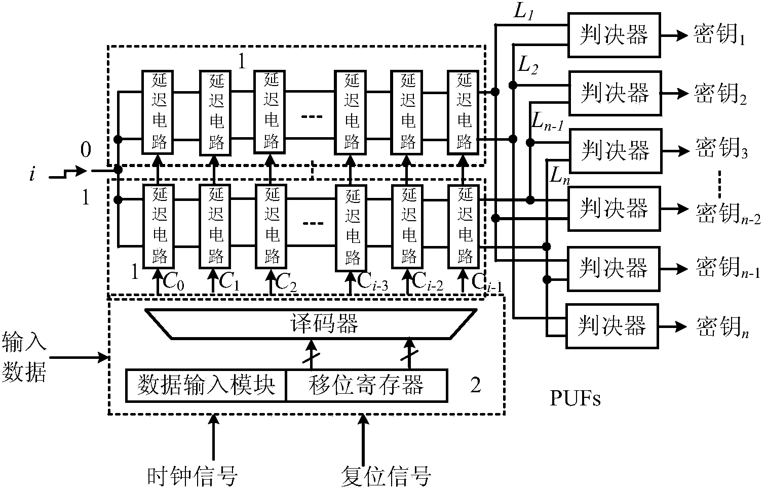
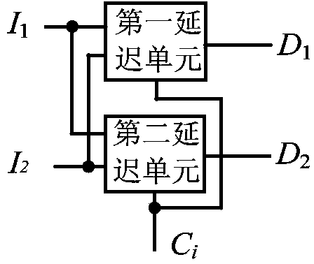
[0035] Embodiment one: if figure 1 As shown, a PUFs circuit based on delay chain multiplexing includes n transmission delay circuits 1 and a controller 2 that generates n control signals for controlling the transmission delay circuits. Two completely symmetrical The signal transmission delay path of n transmission delay circuits has 2n signal transmission delay paths, and the signal output end of each signal transmission delay path outputs a delay signal, and the PUFs circuit also includes A decision device, every two different signal output terminals in the signal output terminals of the 2n signal transmission delay paths are combined into a group of delayed signal output terminals, and the combination is obtained group delay signal output, group delay signal output with The signal input ends of each decision device are connected one by one, and each group of delayed signal output ports outputs a group of delayed signals to a corresponding decision device to generate a ...

Embodiment 2

[0046] Embodiment two: if figure 1 As shown, a PUFs circuit based on delay chain multiplexing includes n transmission delay circuits and a controller that generates n control signals for controlling the transmission delay circuits. Two completely symmetrical signal transmissions are set in the transmission delay circuits Delay path, n transmission delay circuits have 2n signal transmission delay paths, and the signal output end of each signal transmission delay path outputs a delay signal, and the PUFs circuit also includes A decision device, every two different signal output terminals in the signal output terminals of the 2n signal transmission delay paths are combined into a group of delayed signal output terminals, and the combination is obtained group delay signal output, group delay signal output with The signal input ends of each decision device are connected one by one, and each group of delayed signal output ports outputs a group of delayed signals to a correspon...

Embodiment 3

[0054] Embodiment three: as figure 1 As shown, a PUFs circuit based on delay chain multiplexing includes n transmission delay circuits and a controller that generates n control signals for controlling the transmission delay circuits. Two completely symmetrical signal transmissions are set in the transmission delay circuits Delay path, n transmission delay circuits have 2n signal transmission delay paths, and the signal output end of each signal transmission delay path outputs a delay signal, and the PUFs circuit also includes A decision device, every two different signal output terminals in the signal output terminals of the 2n signal transmission delay paths are combined into a group of delayed signal output terminals, and the combination is obtained group delay signal output, group delay signal output with The signal input ends of each decision device are connected one by one, and each group of delayed signal output ports outputs a group of delayed signals to a corresp...


PUM


Abstract

The invention discloses a PUFs (physical unclonable functions) circuit based on transmission delay multiplexing. The PUFs circuit comprises n transmission delay circuits and a controller used for generating n control signals for controlling the transmission delay circuits. Each transmission delay circuit is provided with two signal transmission delay channels which are completely symmetric, and thereby the n transmission delay circuits have 2n signal transmission delay channels. The signal output end of each signal transmission delay channel outputs one delay signal. The PUFs circuit further comprises C22n deciders, every two different signal output ends of the 2n signal transmission delay channels are combined into one group of delay signal output ends, and the C22n groups of delay signal output ends are obtained. The C22n groups of delay signal output ends and the signal input ends of the C22n deciders are correspondingly connected one by one, each group of the delay signal output ends outputs a group of delay signals to one corresponding decider to generate single-bit secret key, and the C22n deciders outputs the C22n secret keys. The PUFs circuit has the advantages that the signal transmission delay channels can be multiplexed maximally, circuit utilization rate is increased and the circuit cost is reduced.

Description

technical field [0001] The invention relates to a physically unclonable function circuit, in particular to a PUFs circuit based on delay chain multiplexing. Background technique [0002] In modern information security systems, physical unclonable function circuits (PUFs circuits) have been widely used as identity authentication and anti-counterfeiting means, such as smart cards, credit cards, RFID tags, Apple mobile phones, security cameras and game devices, etc. Applying PUFs circuits to security devices can effectively defend against traditional attack modes, such as mathematical attacks, virus attacks, differential power consumption attacks, and collision attacks. The PUFs circuit was first proposed by researchers such as Gassend of the Massachusetts Institute of Technology. It is a "DNA feature recognition technology" in the chip field. It extracts the unavoidable process deviation introduced in the chip manufacturing process through the physical unclonable function circ...

Claims


Application Information

Patent Timeline
Patent Type & Authority Applications(China)
IPC IPC(8): G05B19/04
CPCG06F21/71
Inventor 张跃军汪鹏君李建瑞李刚
Owner NINGBO UNIV
Why Eureka
Try Eureka