
Method and device for positioning power transformation equipment on basis of infrared and visible image fusion

A technology for substation equipment and infrared images, which is applied in the fields of instruments, character and pattern recognition, computer parts, etc., can solve the problems of no scale invariance, reduced number of key points, and no direct application, and achieves high engineering application value. , The effect of objective fault detection and significant economic benefits

Active Publication Date: 2015-02-18
NORTH CHINA ELECTRIC POWER UNIV (BAODING)
View PDF4 Cites 22 Cited by
  • Summary
  • Abstract
  • Description
  • Claims
  • Application Information

AI Technical Summary

Problems solved by technology

The SURF (Speed ​​Up Robust Feature) feature point detection algorithm can achieve better detection results when the target is translated, rotated, zoomed, and the brightness changes, but its key point detection algorithm based on the fast Hessian matrix, It is easy to extract a large number of low-unique features from the background edge area with poor information in the image, which leads to a non-negligible mismatch rate; at the same time, the image blur caused by the Gaussian filter makes the algorithm detect the key points in the fusion image target area. The number is reduced, and it is not directly applicable to the fusion image of the substation equipment
The FAST corner detection algorithm can extract the detailed information of the image, but it is not scale-invariant and is easily disturbed by high-frequency noise.

Method used


Image

  • Method and device for positioning power transformation equipment on basis of infrared and visible image fusion
  • Method and device for positioning power transformation equipment on basis of infrared and visible image fusion
  • Method and device for positioning power transformation equipment on basis of infrared and visible image fusion

Examples


Embodiment Construction

[0044] The method proposed by the present invention will be further described below in conjunction with the drawings and embodiments.

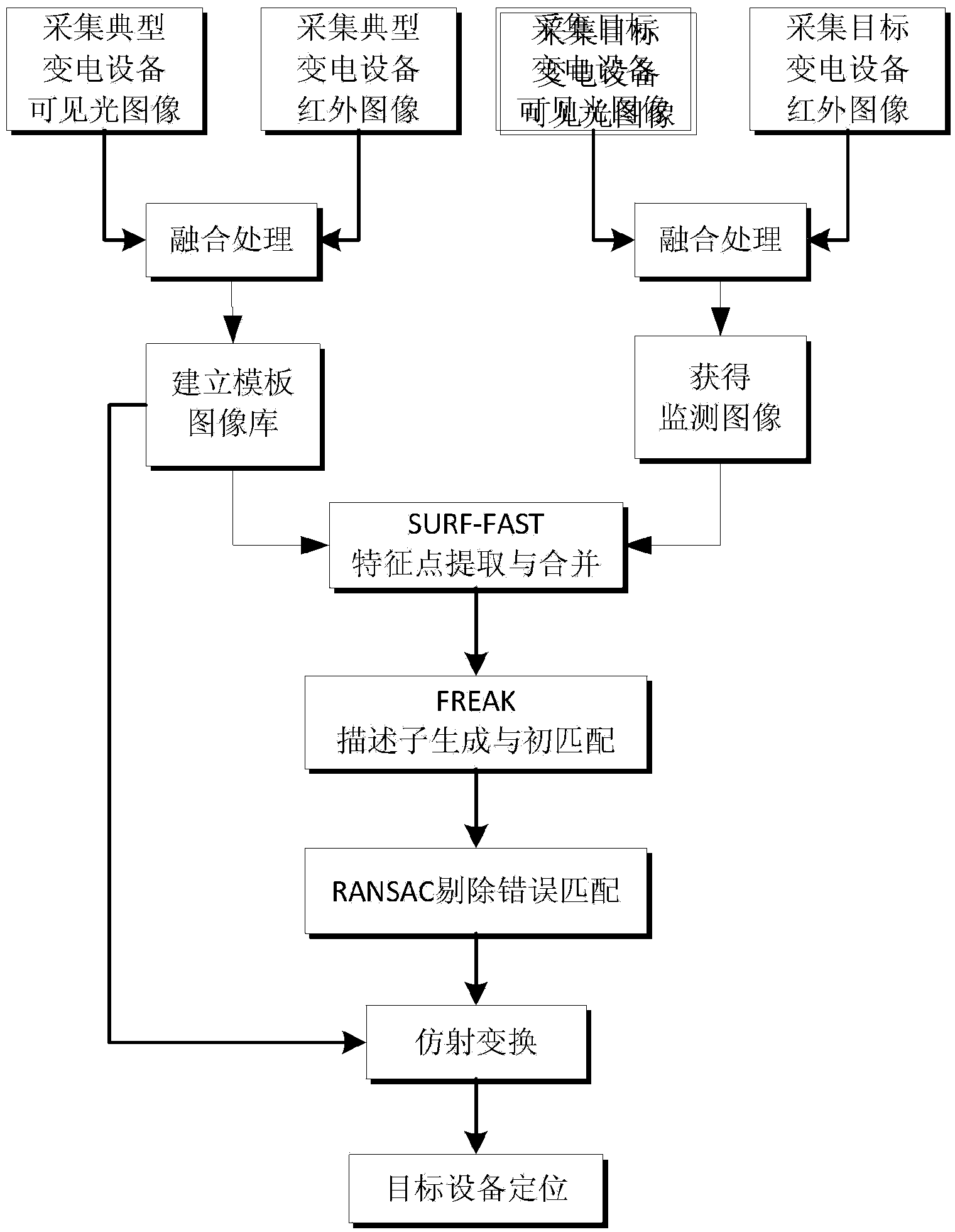
[0045] A positioning method for substation equipment based on fusion of infrared and visible light images, such as figure 1 shown, including:

[0046] Step 1. Collect infrared images and visible light images of typical substation equipment, use the existing pixel-level fusion algorithm to achieve fusion processing of infrared images and visible light images, and establish a template image library for typical substation equipment;

[0047] Step 2. Collect the infrared image and visible light image of the target substation equipment, and use the existing pixel-level fusion algorithm to realize the fusion processing of the infrared image and the visible light image to obtain the monitoring image;

[0048] Step 3, using the SURF-FAST combination algorithm to perform feature point detection on the template image and the monitoring image;

[0049]...


PUM


Abstract

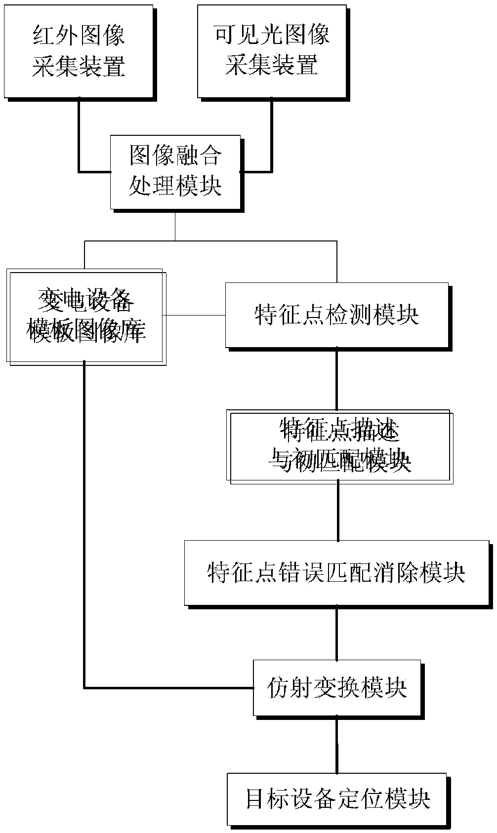
The invention belongs to the field of operating condition maintenance of power transmission and transformation equipment, and particularly relates to a method and a device for positioning power transformation equipment on basis of infrared and visible image fusion. The method includes: acquiring and fusing infrared and visible images of typical power transformation equipment and target power transformation equipment to obtain template images and monitoring images, detecting feature points according to the SURF (speed up robust feature)-FAST combinational algorithm, generating binary descriptors according to the FREAK (fast retina keypoint) algorithm and performing primary matching, and eliminating wrong matches according to the RANSAC (random sample consensus) algorithm; obtaining an affine transformation matrix by means of matrix inverse operation; performing affine transformation to obtain positions of the template images in the monitoring images, and positioning a recognition area of the target power transformation equipment. The device for positioning the power transformation equipment comprises an infrared image acquirer, a visible image acquirer, an image fusion processing module, a power transformation equipment template image base, a feature point detection module, a feature point description and primary matching module, a feature point wrong match eliminating module, an affine transformation module and a target equipment positioning module.

Description

technical field [0001] The invention belongs to the field of operation state maintenance of power transmission and transformation equipment, and in particular relates to a positioning method and device for power transformation equipment based on fusion of infrared and visible light images. Background technique [0002] In the field of substation equipment status monitoring, infrared thermal imaging cameras are often used to detect thermal faults of equipment, but the contrast and clarity of infrared images are poor, while visible light images are rich in details and can clearly reflect the scene information of equipment. Therefore, it is useful on site The dual-channel system constructed with infrared thermal imaging camera and visible light camera as the core device collects the infrared image and visible light image of the equipment at the same time to complete the inspection. However, at present, most infrared and visible light images rely on the subjective analysis of op...

Claims


Application Information

Patent Timeline
IPC IPC(8): G06K9/00
CPCG06V20/38G06V10/757
Inventor 赵振兵徐国智蔡银萍
Owner NORTH CHINA ELECTRIC POWER UNIV (BAODING)
Learn More