Anti-overheating electrical dynamic contact and structure thereof

A technology of moving contacts and contacts, which is applied in the direction of contact surface shape/structure, contact heating/cooling, etc. It can solve the problems of rapid recovery limitation of contacts, difficulty in quickly finding spares, and temperature rise at contact points, etc. , to achieve the effect of preventing contact heating, increasing the effective contact area, and enhancing the flow capacity

Inactive Publication Date: 2015-02-18
HARBIN UNIV OF SCI & TECH +1
View PDF8 Cites 4 Cited by
  • Summary
  • Abstract
  • Description
  • Claims
  • Application Information

AI Technical Summary

Problems solved by technology

The current electrical dynamic contacts are of integral structure. Since the static contacts to be connected have different thicknesses, the contact part of the dynamic contact and the static contact generally adopts an arc structure, so only one line between the two contacts can be maintained. contact surface, prone to heating and arcing
At the same time, once the contact is worn or ablated, it is difficult to quickly find a spare in a short time, and the rapid recovery of the contact is limited.
[0003] At this stage, the application technology in this field is still unable to solve the problems of temperature rise at the contact point caused by mechanical vibration, contact arc ablation, etc., and the problem that it is difficult to recover in a short time once a fault occurs
At present, there are very few domestic patents on this aspect. The Chinese patent "Bridge-type contact device for universal circuit breaker drawer seat" (application number: 201320543033.1) proposes to use bridge-type contacts to replace traditional circuit breaker contacts, and the mechanism is complicated. , although the problem of severe mechanical wear is partially solved, it does not fundamentally solve the problem of the contact surface, as well as the resulting oxidation of the contact, local welding of the contact, generation of sparks and even arc discharge, etc., its safety and reliability and durability can be improved

Method used


Image

  • Anti-overheating electrical dynamic contact and structure thereof
  • Anti-overheating electrical dynamic contact and structure thereof
  • Anti-overheating electrical dynamic contact and structure thereof

Examples


Embodiment Construction

[0021] Below in conjunction with accompanying drawing, the present invention is described in further detail:

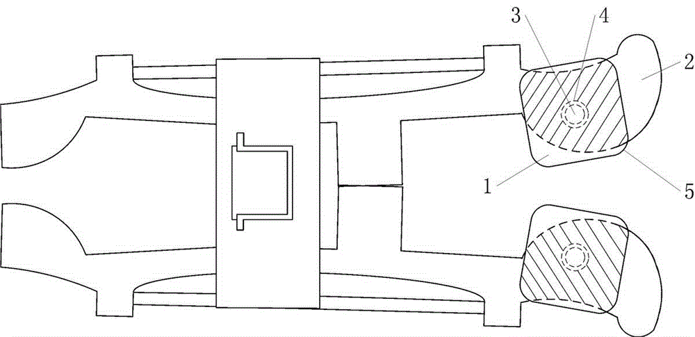
[0022] Such as figure 1 As shown, the moving contact structure of the present invention includes a movable part (1), a support part (2), and a fixed shaft (3). A shaft hole (4) is opened on the movable part (1) and the support part (2), and the fixed shaft (3) passes through the shaft hole (4), and the movable part (1) and the support part (2) are stacked and connected to the Together, make the two in close contact through the upper and lower sides. The electrical connection between the movable part (1) and the support part (2) is realized by close contact between the adjacent upper and lower surfaces, such as figure 1 The shaded part where the middle movable part (1) overlaps with the support part (2).

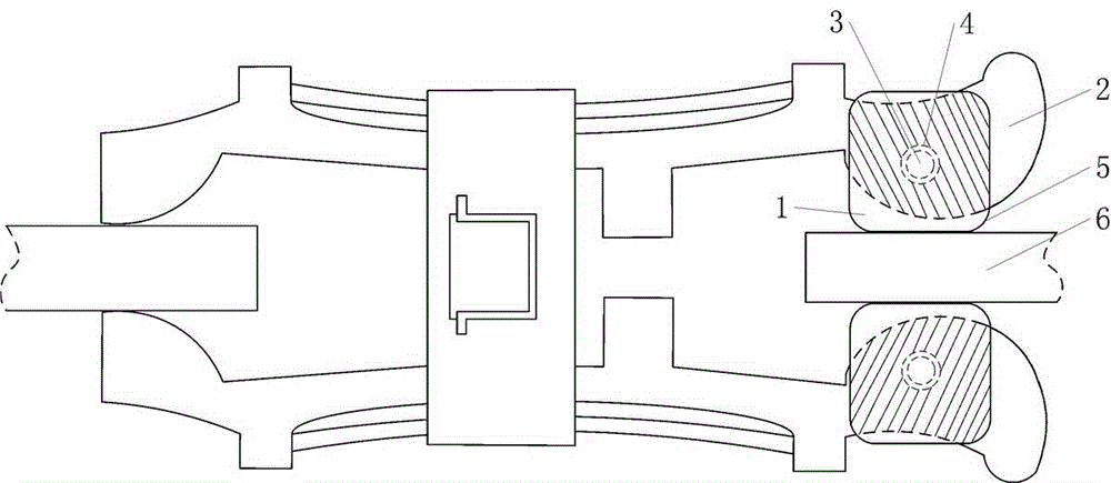
[0023] Such as figure 2 As shown, the movable part (1) of the present invention is a square, the four corners are arc-shaped chamfers (5), and the shaft hole (4...


PUM


Abstract

The invention provides an anti-overheating electrical dynamic contact and a structure thereof, and belongs to the technical field of electrical switches. The anti-overheating electrical dynamic contact comprises moving parts, supporting parts and fixing shafts. The moving parts and the supporting parts are provided with shaft holes, the fixing shafts penetrate through the shaft holes to enable the moving parts and the supporting parts to be connected together after the moving parts and the supporting parts are stacked, and the moving parts and the supporting parts are in close contact through upper faces and lower faces. The dynamic contact can be suitable for static contacts of different thicknesses through the rotation angles of the moving parts, the dynamic contact can be tightly attached to the static contacts through planes, the effective contact area is greatly increased, the phenomena of heating and arcing caused by bad contact are reduced, and the ablation probability of the contact is lowered. Moreover, each moving part is provided with four working faces for standby application mutually, and the through-current capability is improved by overlaying metal sheets of the contact. The anti-overheating electrical dynamic contact has the advantages of being simple in structure, low in cost, high in applicability, good in safety, high in reliability, simple in technology, capable of being widely applied to electrical equipment and measuring equipment such as a disconnecting switch, a pincerlike clamping mechanism and a withdrawable circuit breaker, and the like.

Description

technical field [0001] The invention relates to an electrical switch contact, in particular to a movable contact of an electrical switch capable of preventing overheating and its structure. It belongs to the technical field of electrical switches. Background technique [0002] Because plug-in circuit breakers, isolating switches, electrical equipment and clamping mechanisms of measuring equipment do not have arc extinguishing functions, they should be strictly prevented from heating and causing more serious faults such as arcing when used. The current electrical dynamic contacts are of integral structure. Since the static contacts to be connected have different thicknesses, the contact part of the dynamic contact and the static contact generally adopts an arc structure, so only one line between the two contacts can be maintained. The contact surface is prone to heating and arcing. At the same time, once the contact is worn or ablated, it is difficult to quickly find a spar...

Claims


Application Information

Patent Timeline
Patent Type & Authority Applications(China)
IPC IPC(8): H01H1/06H01H1/62
CPCH01H1/06H01H1/62
Inventor 周封周至柔王丙全郝婷刘健王晨光崔博闻刘小可朱瑞
Owner HARBIN UNIV OF SCI & TECH
Why Eureka
Try Eureka